
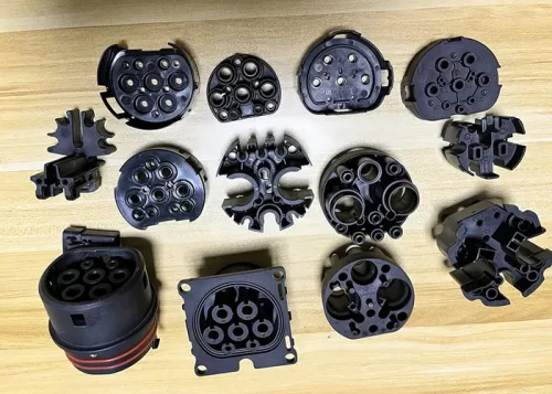





Injection molding is a widely used manufacturing process, but it easily produces a range of typical defects that can affect product appearance, mechanical performance, and long-term reliability.
Material properties, mold design, and processing parameters influence these defects, such as cracking, short shot, flash, weld lines, and warpage.
Understanding their root causes is essential for effective quality control and process optimization.
Cracking
Cracking is a very common surface defect of plastic products, mainly caused by deformation of materials under stress.
Stresses fall into three categories: residual stress, external stress and environmental stress.
Cracking Caused by Residual Stresses
The following three factors primarily cause residual stresses: overfilling, ejection during demolding, and metal inserts.
Reducing Cracks Caused by Overfilling
Cracks caused by overfilling can be addressed from the following aspects:
1. Since straight gates result in the least pressure loss, if cracking occurs primarily near the straight gate, consider switching to multi-point distributed gates, side gates, or handle-shaped gates.
2. While ensuring the resin does not decompose or degrade, appropriately increasing the resin temperature can reduce melt viscosity and improve flowability.
This also allows for a reduction in injection pressure, thereby minimizing stress.
3. In general, lower mold temperatures are more likely to cause stress, so the temperature should be appropriately increased.
However, when injection speed is high, stress can be reduced even at slightly lower mold temperatures.
4. Excessively long injection and holding times can also generate stress;
Shortening these times appropriately or performing multiple holding-pressure cycles yields better results.
5. Your sentences are already in active voice, so no structural conversion is needed. Here is a slightly smoother active-voice rewrite for flow and clarity:
Stress Generated During Demolding
In general, lower mold temperatures are more likely to induce stress, so the temperature should be increased appropriately.
However, when injection speed is high, stress can still be reduced even if the mold temperature is slightly lower.
During ejection, a small draft angle combined with rough mold cavities and ejector pins can result in excessive ejection force, generating stress.
This can sometimes even cause whitening or cracking around the ejector pins.
Careful observation of the location where cracking occurs can help determine the cause.
Cracking Caused by Metal Inserts
Embedding metal inserts during injection molding most often leads to stress, and cracks may not appear until some time has passed, posing a significant hazard.
This is primarily due to the stress caused by the significant difference in thermal expansion coefficients between the metal and the resin;
Over time, this stress exceeds the strength of the gradually deteriorating resin material, leading to cracks.
To prevent such cracking, general-purpose polystyrene—where the wall thickness corresponds to the outer diameter of the embedded metal part—is generally unsuitable for inserts, whereas inserts have the least effect on nylon.
Since glass-fiber-reinforced resin materials have a lower coefficient of thermal expansion, they are more suitable for inserts.
Additionally, preheating metal inserts before molding yields good results.
Cracking Caused by External Stresses
The external stresses referred to here are primarily stress concentrations resulting from improper design;
Particular attention must be paid to sharp corners.
Cracking Caused by External Environmental Factors
Chemical agents, water degradation caused by moisture absorption, and excessive use of recycled materials can all degrade physical properties and lead to cracking.
Short Shot
Short shot refers to incomplete filling of mold cavities by molten plastic, mainly attributed to insufficient resin feeding volume, inadequate cavity packing pressure, poor melt flowability and poor mold venting.
Improvement measures:
1)Extend injection time to avoid short shot caused by melt backflow before gate solidification due to an overly short molding cycle.
2)Increase injection speed.
3)Raise mold temperature.
4)Elevate resin temperature in the barrel.
5)Boost injection pressure.
6)Enlarge gate size; the recommended gate thickness is 1/2 ~ 1/3 of the product wall thickness.
7)Position gates at areas with the maximum product wall thickness.
8)Set up vent slots (conventional depth: 0.03 mm, width: 3–5 mm) or install vent ejector pins, which is especially critical for small workpieces.
9)Reserve cushion stroke between the screw and nozzle.
10)Select raw materials with low viscosity grades.
11)Add plastic lubricants.
Wrinkles and Matte Surface Pitting
The root cause of this defect is identical to that of short shot, differing only in severity, so most optimization solutions for short shot are also applicable.
For raw materials with poor flowability (polyoxymethylene, PMMA, PC, PP, etc.), appropriately enlarge gate dimensions and prolong injection duration.
Sink Marks
The formation mechanism of sink marks is consistent with short shot.
In theory, overfilling can improve sink marks, but it increases the risk of cracking caused by residual stress.
At the design stage, designers must ensure uniform wall thickness and minimize thickness variations at ribs and bosses as much as possible.
Flash
Mold structural optimization takes priority in improving flash, and reducing melt flowability allows engineers to adjust the molding process.
The specific solutions are listed below:
1)Reduce injection pressure.
2)Lower resin temperature.
3)Switch to raw materials with higher viscosity grades.
4)Decrease mold temperature.
5)Grind and repair mold parting surfaces where flash occurs.
6)Adopt mold steel with higher hardness.
7)Increase clamping force.
8)Conduct precise mold fitting to ensure tight lamination of mold parting surfaces.
8)Add support pillars to enhance overall mold rigidity.
10)Match vent slot specifications for different types of raw materials.
Weld Lines
Weld lines form when two or more converging melt fronts cool down and fail to fuse sufficiently.
Mild weld lines only impair appearance and adversely affect subsequent spraying and electroplating processes;
Severe weld lines drastically reduce product strength, with more prominent adverse impacts on glass fiber-reinforced plastics.
Improvement methods:
1) Adjust molding parameters to boost melt flowability: raise barrel temperature, mold temperature, injection pressure and injection speed.
2) Add vent slots and arrange ejector pins at positions corresponding to weld lines for auxiliary venting.
3) Reduce the spraying amount of mold release agent.
4) Runners should be designed so that weld lines are transferred onto the runners, which can then be trimmed after molding.
5) If only appearance is affected, gate positions can be adjusted to change weld line distribution, or matte finishing can be applied to weld line areas to conceal defects.
Burn Marks
Three categories of causes lead to burn marks: mechanical equipment faults, mold issues and improper molding processes, with targeted solutions respectively.
1) Mechanical failures: Abnormally high barrel temperature causes resin carbonization via thermal decomposition, and decomposed material enters the cavity through injection;
Or stagnant melt at the nozzle, screw threads and check valve decomposes, discolors and forms dark brown burn marks on products.
Solution: Thoroughly clean the nozzle, screw and barrel.
2) Mold problems occur when poor venting traps air that burns under compression, producing burn marks at fixed positions that can be clearly distinguished from mechanically induced burns.
Solution: Add vent slots and vent ejector pins.
3)Parameter issues: Backpressure exceeding 300 MPa triggers local overheating inside the barrel;
Excessively high screw speed also leads to temperature rise, so the rotational speed is recommended to be controlled within 40–90 r/min.
In the absence of vents or with undersized vents, high-speed injection compresses air and burns product surfaces under high temperature.
Silver Streaks
Silver streaks are mainly caused by moisture absorption of raw materials.
Conventional drying temperature is set 10–15 °C lower than the resin heat deflection temperature; high-spec PMMA requires drying at 75 °C for 4–6 hours.
When equipped with an automatic drying hopper, match hopper capacity with production capacity and drying duration, and start drying several hours in advance before injection molding startup.
In addition, excessively long melt residence time inside the barrel and blending of incompatible materials (polystyrene + ABS/AS, polypropylene + polystyrene, etc.) can also generate silver streaks. Mixing dissimilar materials is prohibited.
Jetting
Jetting refers to serpentine curved stripes formed along the flow direction as melt ejects at high velocity from the gate, fundamentally resulting from excessive injection speed at the gate.
Improvement solutions: Enlarge gate cross-sectional area and reduce injection speed;
Raise mold temperature to slow down cooling of melt upon contact with cavity walls, prevent rapid solidification of the surface layer at the initial filling stage, and alleviate jetting defects.
Voids
Voids are divided into two types by formation causes, with corresponding treatments as follows:
Vacuum Voids (Shrinkage Cavities at the Center of Thick-Walled Products)
The surface layer of thick-walled products cools far faster than the interior.
Shrinkage of central melt during cooling pulls inward and forms hollow cavities.
Solutions:
a) Design reasonably sized gates and runners according to product wall thickness; gate thickness accounts for 50%–60% of product wall thickness.
b) Maintain sufficient feeding volume before gate freezing.
c) Set injection time slightly longer than gate solidification time.
d) Reduce injection speed and increase injection pressure. e) Select raw materials with high melt viscosity.
Voids from Volatile Gases
Voids generated by raw material decomposition and water vapor volatilization.
Improvement solutions:
a) Fully pre-dry raw materials.
b) Lower barrel temperature to avoid gas generation from thermal decomposition of resin.
Voids Induced by Insufficient Flowability
Eliminate such voids by increasing resin temperature and mold temperature as well as injection speed to improve melt flowability.
Whitening
Whitening frequently occurs in ejection areas of ABS products, mainly caused by excessive demolding resistance.
Improvement approaches: Reduce injection pressure, increase draft angle, add more ejector pins or enlarge ejector pin cross-sectional area, lower mold surface roughness;
Mold release agent can also be sprayed, provided that subsequent processes such as hot stamping and painting are not adversely affected.
Warpage and Deformation
Warpage of injection-molded parts is difficult to control, and optimization mainly relies on mold design, while process adjustment delivers limited improvement effects.
Causes of deformation and corresponding solutions are listed below:
1)Deformation from molding stress: Reduce injection pressure, uniformly raise overall mold temperature and barrel temperature, or adopt annealing to eliminate internal stress.
Deformation caused by demolding resistance: Increase the number of ejector pins, expand ejection area and enlarge draft angle.
2)Uneven cooling or insufficient cooling duration: Optimize cooling channel layout, extend cooling time, and arrange cooling circuits close to deformed areas.
3)Deformation from differential molding shrinkage: Modify mold structure to prioritize uniform product wall thickness;
If necessary, measure product deformation and conduct reverse mold modification to counteract shrinkage deformation.
4)Crystalline resins (polyoxymethylene, nylon, PP, PE, PET, etc.) feature higher shrinkage rates and produce more severely deformed finished products compared with amorphous resins (PMMA, PVC, PS, ABS, AS, etc.).
Warpage and deformation are also more obvious for glass fiber-reinforced plastics due to fiber orientation.
Conclusion
Most injection molding defects can be mitigated through a combination of optimized mold design, proper material selection, and precise control of processing conditions such as temperature, pressure, cooling, and injection speed.
While some issues originate from structural limitations, many can be significantly reduced by balancing flow behavior, stress distribution, and cooling uniformity.
A systematic approach to troubleshooting ensures stable production, improved product quality, and reduced manufacturing costs.