





In practical applications, trapezoidal groove flanges primarily achieve a good seal through full contact between the gasket and the flange sealing surface;
Their unique structural design places high demands on the shape, position, and fit accuracy of the sealing groove.
A cast iron inlet pipe produced by our company for export uses this trapezoidal groove flange sealing design.
The part has thin walls. It easily deforms when being machined.
Besides, the trapezoidal groove’s machining center must be precisely positioned relative to the casting center of the flow channel.
The positioning standards here are extremely strict.
For these reasons, this workpiece is classified as a high-precision trapezoidal groove flange.
At the outset of development, we experimented with various conventional machining methods, such as linear and circular interpolation on CNC lathes and programmed milling on machining centers;
However, none of these methods could fully meet the drawing specifications.
This article presents a new machining process. The process mainly uses customized cutting tools. It also adopts center-alignment technology.
These two methods work together to solve the machining difficulties of high-precision trapezoidal groove flanges.
Technical Requirements for Trapezoidal Groove Flange Machining
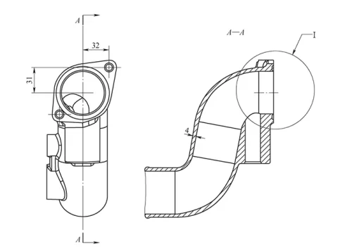
As shown in Figure 1, the wall thickness of the trapezoidal groove flange is (4±0.5) mm; the pipe wall is thin and the outer shape is irregular.
The casting diameter of the flow channel is (52 ± 0.5) mm; the machined outer diameter of the trapezoidal groove opening is 64 + 0.19 + 0 mm;
The angle between the groove side and the groove bottom is machined to 95° ± 0.3°;
The groove bottom fillet radius R is (0.45 ± 0.3) mm; the opening fillet radius R is (0.2 ± 0.05) mm;
The groove bottom width is (4.7 ± 0.13) mm, the groove depth is (2.66 ± 0.12) mm, and the surface roughness value Ra is 2.5 μm. In terms of geometric accuracy:
The hole opening radius R is (0.2 ± 0.05) mm, and the surface roughness Ra of the groove bottom and sides is 2.5 μm.
These requirements are stringent, and factors such as tool wear, part deformation due to stress, and tool vibration during machining can all affect the machined dimensions.
We will first discuss positional accuracy.
The machining center of the trapezoidal groove and the casting center of the runner should be concentric in theory.
In addition, there is a theoretical spacing of 0.8 mm between the opening of the trapezoidal groove and the casting opening of the runner.
For machine-cast gray iron parts, this dimensional tolerance range is relatively narrow;
Even minor fluctuations during machining are highly likely to cause issues such as notches in the trapezoidal groove or flash at the opening, thereby affecting performance.
Original Machining Process and Problem Analysis
CNC Lathe Linear and Arc Interpolation Turning + Radial Drill Press Drilling Process
1. OP10: CNC Turning of Flange and Trapezoidal Groove
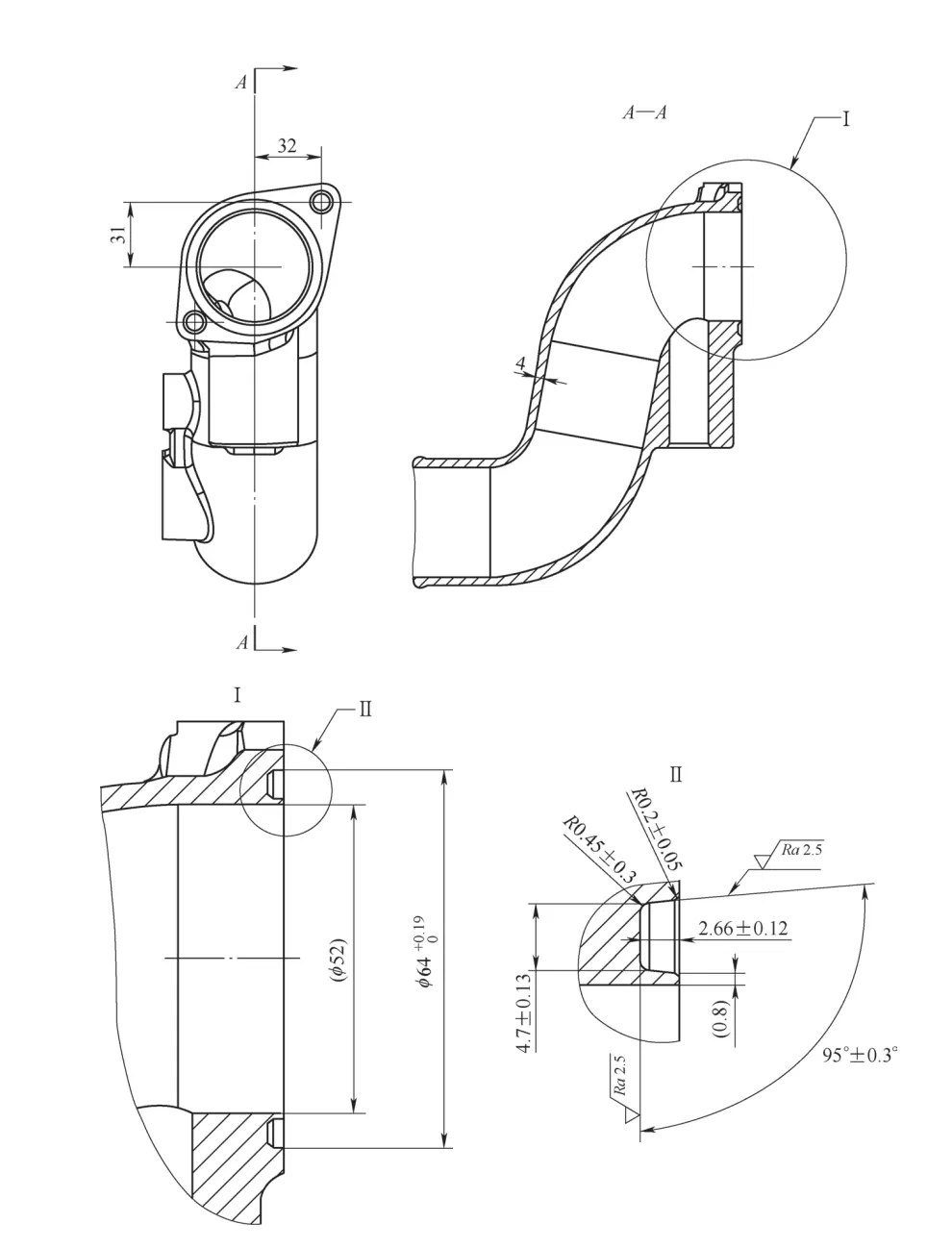
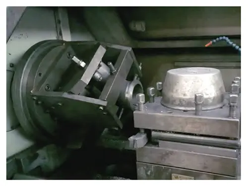
OP10: Using the blank’s outer contour for positioning, perform rough and finish turning of the flange surface and interpolation turning of the trapezoidal groove on a CNC lathe using arc interpolation.
The CNC turning process is shown in Figure 2.
2. OP20: Drilling of Bolt-Through Holes
OP20: Using the machined flange surface, its flow channels, and the blank’s outline as reference points, a conventional radial drill press is used to drill bolt-through holes in the flange surface.
3. Process Limitations and Deficiencies
The process has the following shortcomings:
1) This machining process places high demands on blank consistency.
As a machine sand-cast part, the blank typically has casting tolerances of CT9 to CT10 grade.
With large casting tolerances and generally average casting accuracy, casting defects such as box expansion and misalignment significantly affect the machining results.
2) Workpieces can be positioned by relying on the outer contour of the blank.
This positioning method uses the outer contour as the positioning reference.
Meanwhile, the runner center serves as the design reference.
Any offset between these two references will create positioning errors.
Lathe equipment is not equipped with functions to detect and compensate for errors.
There is a theoretical critical tolerance of ±0.3 mm for center alignment.
This tolerance applies to the trapezoidal groove machining center and the runner casting center.
If their offset goes beyond ±0.3 mm, defects will form on the hole opening.
Such defects include flash, and in severe cases, notches.
3) Low yield rate and high processing costs. The cutting edge width of the end-face groove is (4 ± 0.025) mm, with an R-radius of (0.2 ± 0.05) mm.
These are precision grooving inserts that are sharp and prone to wear, requiring frequent tool changes.
Combined with an overall yield rate of only about 20%, this results in high processing costs.
4) The bolt holes in the flange face are machined using a standard drill bit guided by a drill jig.
This process also relies on the blank’s outer contour for positioning.
If there is a significant deviation between the centerline connecting the two bolt holes and the center of the sealing groove, it will affect the product’s performance.
Machining Center Programming: Milling + Center Pin Edge Detection Process
The machining center programming for milling and the center pin edge detection process are shown in Figure 3. The specific procedure is as follows.
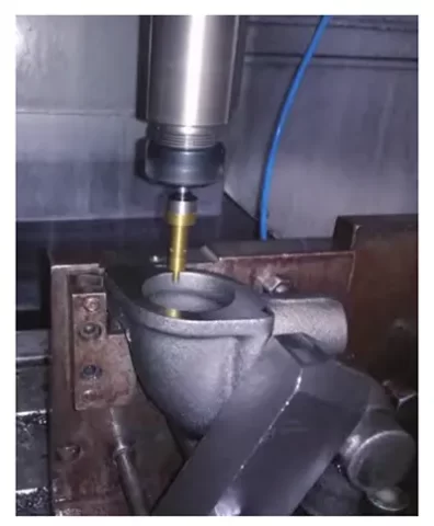
1) Use a cutter head to perform rough and finish milling of the flange surface.
2) Pause the machine, load the centering rod into the machining center’s chuck, and have the operator turn the handwheel to bring the centering rod into contact with the sidewall of the flow channel.
Based on the display on the machining center’s control panel, the operator calculates the center of the flow channel and adjusts the program accordingly.
3) Use a carbide end mill to mill trapezoidal grooves and drill bolt-through holes as programmed.
Process Disadvantages:
① High requirements for blank consistency; manual centering is required, resulting in low machining efficiency.
② Conventional cutting tools cannot produce trapezoidal grooves that meet specifications;
That is, the shape of the trapezoidal grooves does not fully satisfy the drawing requirements.
Improvement Measures
The processing relies on one machining center and one set of special fixtures.
It also matches customized cutting tools and equipment center alignment technology.
With all these conditions, high-precision trapezoidal groove flanges can be finished in a single clamping setup.
Custom Trapezoidal Groove Forming Tool Design
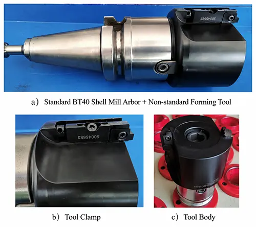
Design and manufacture a custom trapezoidal groove forming tool (see Figure 4) to ensure the dimensional accuracy of the trapezoidal groove.
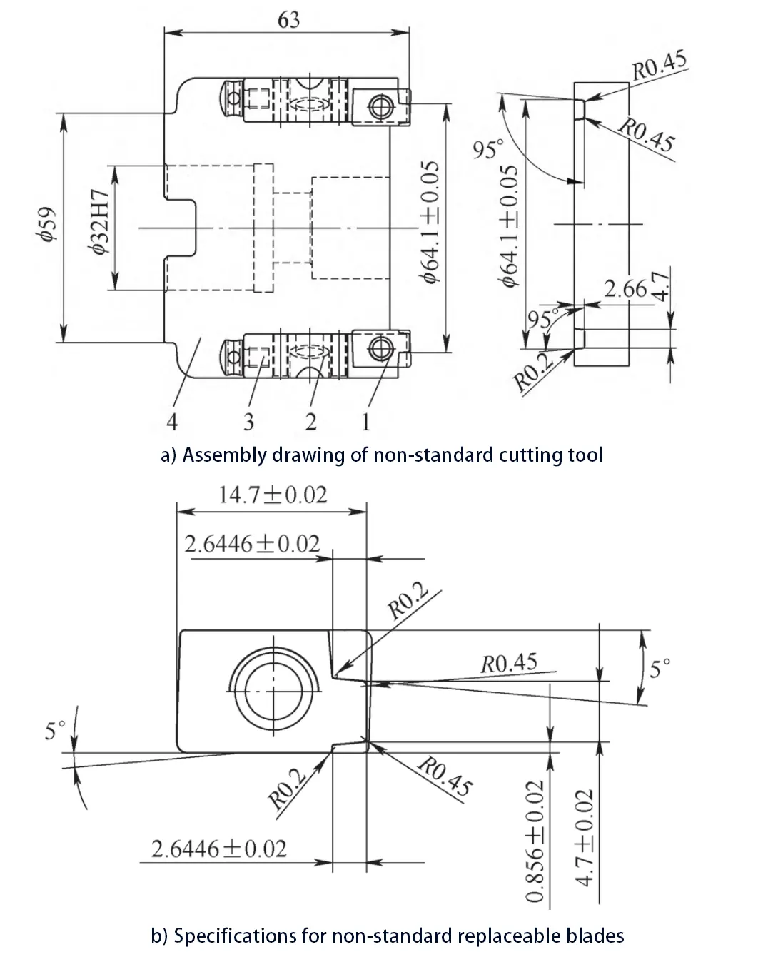
The tool design parameters are shown in Figure 5.
The tool primarily consists of a tool body (4), a tool holder (2), and a custom replaceable insert (1).
The shank is a standard BT40-X M32-75 sleeve-type milling shank.
The tool body is mounted on the φ32g6 arbor of the sleeve-type milling shank and secured with a hexagonal socket head cap screw;
Torque is transmitted via keyways on both sides.
The tool body features two tool pockets equipped with two small tool holders.
These holders are positioned within the pockets to mount the custom-made indexable inserts and are secured together with screws.
One tool holder features a fine-adjustment screw numbered No. 3 on the top.
This component makes Z-axis adjustment much easier. It ensures uniform force on the cutting tool.
Vibration during machining can be reduced as a result. Meanwhile, the surface finish of the trapezoidal groove bottom gets improved.
The cutting inserts adopt YG6 tungsten carbide as base material.
A coating layer of TiC or TiN is applied on the inserts. The thickness of this coating ranges from 5 to 10 micrometers.
The coating boosts the surface wear resistance of inserts. It also effectively prolongs the service life of the cutting inserts.
Machine Tool Probe for Automatic Center Alignment
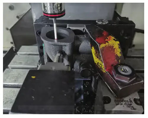
Upgrade the machining center’s software system by installing a machine tool probe and the corresponding operating programs to enable the machining center’s center-alignment function.
The machine tool adopts a contact-type probe.
Operators only need to let the probe gently touch the edge of the workpiece flow channel during operation.
The built-in program will carry out relevant calculation work afterward.
It can automatically complete the centering calibration of the workpiece inside the machine.
This function controls the offset between the trapezoidal groove machining center and the flow channel casting center within ±0.2 mm.
The hydraulic fixture and machine tool probe are shown in Figure 6.
Hydraulic Fixture for Positioning and Rigidity
Design a hydraulic fixture to enhance rigidity, ensuring accurate workpiece positioning and secure clamping.
This measure can stop the workpiece from shifting under cutting forces.
It also avoids multiple machining defects. One common defect is deformation generated by clamping force.
Another problem is vibration marks appearing on the bottom of the trapezoidal groove.
Such marks come from tool vibration during cutting operations.
Optimized Machining Process and Results
Optimized Machining Process
The optimized machining process is as follows.
1) After positioning and clamping the product in a hydraulic fixture using its outer contours, rough and finish mill the flange surface using a cutter head.
2) Retrieve the contact probe from the tool magazine to automatically take measurement points according to the instructions in the program; perform in-process calculations to align the center.
3) Retrieve the custom trapezoidal groove forming tool from the tool magazine to mill the trapezoidal groove.
4) Retrieve a carbide drill from the tool magazine to drill two bolt-through holes.
Results Verification
The results of the process improvements are as follows.
1. Cutting Tool Performance and Cost Optimization
1) Through the design, manufacture, and application of custom-made cutting tools, the overall geometric accuracy of the trapezoidal groove flanges has been steadily improved;
The surface roughness and fillet radii of the trapezoidal grooves fully meet the drawing specifications.
2) The custom-made cutting inserts feature a surface coating process, making them more wear-resistant, durable, and easy to replace.
There used to be an older machining process. Each standard cutting tool for that process cost around 2 yuan.
In addition, the corresponding product yield was low back then.
Now we use an improved process. The cost of each customized cutting tool is only about 0.5 yuan.
This change cuts the total tooling cost by 75 percent.
2. Center Alignment and Positional Accuracy Control
1) The application of automatic center alignment technology has significantly improved machining efficiency and the overall positional accuracy of the trapezoidal groove flanges.
The deviation between the trapezoidal groove machining center and the flow channel casting center can be stably controlled within ±0.2 mm, with a 100% pass rate.
2) In a single setup during the same process step, both the trapezoidal groove and the two bolt-through holes can be machined simultaneously.
This method effectively controls a key dimensional deviation.
The deviation refers to the centerline of the two bolt through-holes relative to the sealing groove center.
It keeps this error within the tolerance of ±0.1 mm. As a result, the overall working performance of the product is reliably guaranteed.
3. Fixture Improvement and Overall Process Outcomes
1) The use of hydraulic fixtures allows for adjustable and controllable force distribution across all parts of this thin-walled component.
The workpiece achieves precise positioning and stable support. It also obtains more reliable clamping force.
These advantages effectively suppress common machining defects.
The defects include tool vibration and clamping-induced deformation.
In turn, stable processing conditions secure consistent product quality.
The old machining method had two frequent flaws. One was vibration marks left on workpieces due to low fixture rigidity.
The other was unstable dimensions from stressed product deformation.
The new process fully erases all these two types of problems.
2) The overall yield rate of the product has significantly increased from approximately 20% to 95%, and machining efficiency has improved nearly fivefold.
Practice has proven that this process is highly suitable for machining high-precision trapezoidal groove flanges on sand-molded thin-walled cast iron water inlet pipes.
Conclusion
This case takes a trapezoidal groove flange as the research object.
The flange relies on full contact between the gasket and its sealing surface to realize sealing performance.
This working principle raises strict requirements for the sealing groove.
High precision must be maintained in its shape, position and assembly fit.
One critical requirement is precise coaxiality. The trapezoidal groove machining center must be perfectly aligned with the flow channel casting center.
Traditional machining and centering techniques cannot satisfy the dimensional standards specified on engineering drawings.
The optimized new process utilizes one machining center and one set of specialized fixtures.
By employing custom-made cutting tools in conjunction with the machine’s automatic centering technology, the entire machining process is completed in a single setup.
This processing method solves multiple typical machining defects of trapezoidal grooves.
These defects include concentricity errors and out-of-tolerance profile shapes.
It also eliminates chatter marks left by cutting tools on the groove bottom.
All these improvements lift the overall product quality. Meanwhile, the machining efficiency is also greatly increased.
The method makes full use of three core technologies.
They are custom cutting tools, hydraulic fixtures, and the automatic centering function of the machining center.
These technologies jointly satisfy the strict processing standards for trapezoidal groove flanges.
The new method successfully fixes all drawbacks of the old processing flow.
It proves outstanding practical value and innovative features in actual production.