
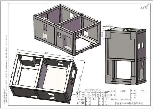





Sheet metal fabrication is a cornerstone of modern manufacturing, powering everything from electronic enclosures to industrial machinery.
However, achieving high-quality, cost-effective sheet metal parts requires careful attention to design details that directly impact manufacturing efficiency, tool longevity, and final product performance.
This article explores the key design considerations across four critical areas of sheet metal production: punching, bending, screw hole design, and enclosure construction.
From hole spacing and shape selection to bend radii and stiffening ribs, from screw fastening methods to EMI shielding strategies, each design decision carries practical consequences for production costs, maintenance requirements, and end-product quality.
Understanding these principles is essential for engineers and designers seeking to optimize manufacturability while minimizing downtime, defects, and unnecessary expenses.
Key Design Considerations for Sheet Metal Punching
For two adjacent holes, the shortest distance from the edge of one hole to the edge of the other should ideally be no less than 1.5 times the material thickness.
Otherwise, the die is prone to cracking, which can cause production line downtime;
Downtime and die repairs are major factors contributing to increased costs and reduced profits.
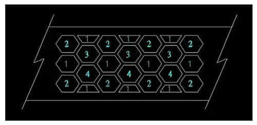
If it is absolutely necessary to have a distance less than 1.5 times the material thickness, a staggered arrangement must be used.
Structural Selection and Service Life Comparison of Different Hole Shapes
In die manufacturing, round holes are the most robust and easiest to produce and maintain, though they offer a lower open area ratio.
Square holes provide the highest open area ratio; however, because they feature 90-degree angles, the corners are prone to wear and collapse, leading to die repairs and production line stoppages.
Hexagonal “honeycomb” holes, with their 120-degree angles (greater than 90 degrees), are more robust than square holes but have a slightly lower open area ratio at the edges compared to square holes.
Burr Control and Drawing Marking Requirements for Punching Parts
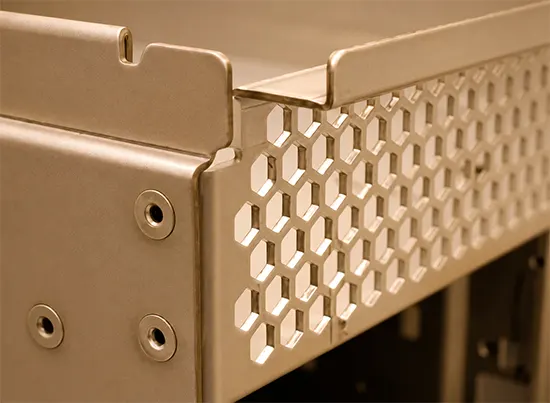
During blanking and punching of sheet metal, rounded corners and burrs may form.
This is especially true during mass production, once the die has worn down to a certain extent; burrs can become more severe and may even cut your fingers.
Therefore, when creating drawings for die fabrication, the direction of the burrs must be clearly indicated based on the part’s function.
Cross-Section Characteristics and Dimensional Calibration Standards of Blanking Surfaces
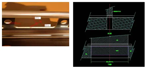
During blanking and punching of sheet metal, the cut surface closest to the punch (1/3 to 2/5 of the way from the punch) is a flat cut surface, while the portion closest to the die (3/5 to 2/3 of the way from the punch) is an angled tear surface.
Therefore, when manufacturing dies or checking dimensions, the hole diameter is determined based on the punch.
During blanking, the external dimensions of the workpiece are determined based on the internal dimensions of the die.
Key Points for Sheet Metal Bending Design
Basic Bend Geometry and Radius Design
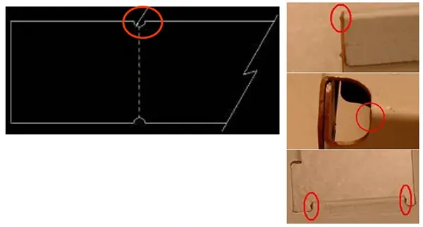
After bending, metal material tends to protrude on both sides of the bend due to material compression.
This results in a width greater than the original dimension, and the extent of the protrusion depends on the material thickness—the thicker the material, the greater the protrusion.
To prevent this from occurring, create a semicircle on both sides of the bend line beforehand; the diameter of the semicircle
should ideally be at least 1.5 times the material thickness. Apply the same method when designing folded edges.
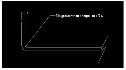
When bending sheet metal, the internal radius (R) should preferably be greater than or equal to half the material thickness.
If no radius is added, the right angle will gradually disappear after repeated stamping, naturally forming a radius.
Afterward, the length on one or both sides of this radius will increase slightly.
Structural Reinforcement and Stiffness Enhancement
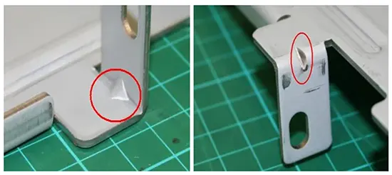
Sheet metal is prone to deformation when subjected to stress after bending.
To prevent deformation, appropriate 45-degree stiffening ribs can be added at the bend points, ensuring they do not interfere with other components, thereby increasing the strength of the part.
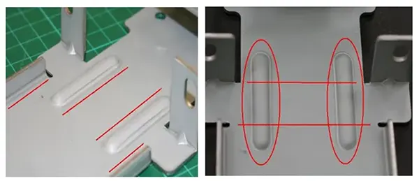
Generally, when sheet metal parts are long and narrow, it is difficult to maintain their straightness, and they are more prone to deformation when subjected to force.
Therefore, we can bend one edge to form an L-shape or bend two edges to form a U-shape to maintain their strength and straightness.
However, what should we do when the L- or U-shape cannot extend from one end to the other—that is, when it is interrupted due to certain factors?
We can add an appropriate number of ribs to increase its strength.
Hole Placement, Edge Corners and Folded Edge Details
1. Hole Design at Bend Transitions and Die Radius Requirements
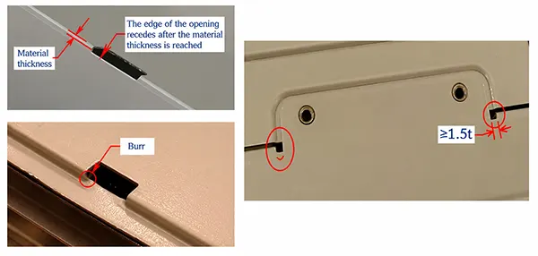
It is best to include narrow holes at the transition between flat and bent surfaces, or to position the edges of openings so they extend beyond the bend.
Otherwise, burrs will form. The width of the narrow holes should be at least 1.5 times the material thickness.
Also, when drafting, do not forget to specify the R-radius—or take shortcuts by omitting it.
Male and female dies with right angles or acute angles are prone to cracking.
Subsequent production line downtime and die repairs will result in additional losses.
2. Edge Corner Radius and Folded Edge Specifications
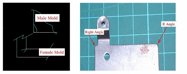
At the corners of metal sheet edges, unless otherwise specified, a 90-degree angle should be replaced with an appropriate radius (R).
This is because right angles at the edges of metal sheets can create sharp points that may cause cuts to workers.
In the female mold, the sharp tips of right angles are prone to cracking due to stress concentration.
In the male mold, the tips are prone to chipping, requiring mold repairs that delay mass production.
Even if chipping does not occur, wear and tear will eventually create rounded corners over time, resulting in burrs on the product and causing defects.
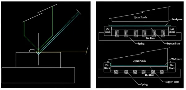
Folded edges can be either single-sided or double-sided. If precision is required, it is best to use double-sided folds, as they offer greater accuracy.
The height of the folded edge should preferably be greater than 3 mm (t: 1.0–1.2 mm);
Otherwise, the dimensions may be unstable due to insufficient clamping area.
3. Side Wall Feature Design and Defect Prevention
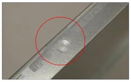
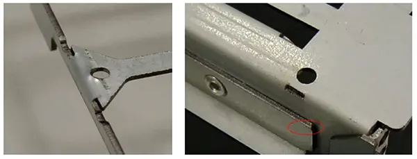
1. When bending the edge, parts or internal protrusions on the side wall should not be too close to the bottom surface—preferably at least 10 mm away.
Otherwise, since there is no die to punch the R-corner beneath the protrusion, that R-corner will be larger than the R-corners on either side.
Discontinuous R-corners will affect the appearance.
To resolve this, a crease of appropriate length can be punched along the bend line before bending, which will improve the appearance.
2. When bending the edge, the holes in the edge wall should not be too close to the bottom surface;
Ideally, they should be at least 3 mm away. Otherwise, the holes will deform due to the stress caused by the bending.
To solve this problem, before bending, punch a long slit along the bend line that is as long as the hole and 1.5 times the thickness of the material wide.
This slit will interrupt the stress without affecting the appearance of the hole.
Key Considerations for Screw Hole Design
There are generally three methods for securing screws:
Direct Hole Threading Methods
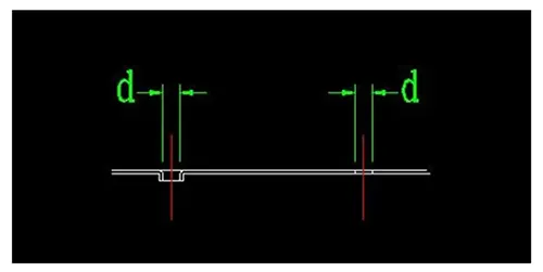
1. Punching holes (through holes) or drawing holes directly into the flat surface of a metal part, using self-tapping screws.
Triangular self-tapping screws are preferable, as they are less likely to strip the threads.
However, they require slightly more torque to tighten than non-triangular self-tapping screws.
When fastening with a 3 mm diameter screw, the hole diameter d should be between 2.4 and 2.5 mm.
When fastening with a 4 mm diameter screw, the hole diameter d should be between 3.4 and 3.5 mm.
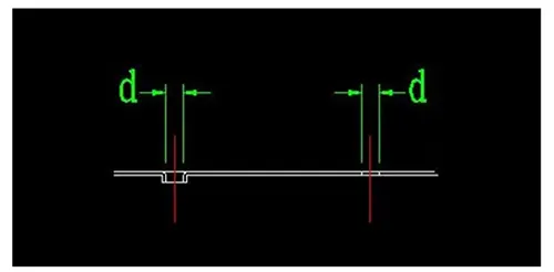
2. Punch through holes or drawing holes in the flat surface of the metal part, then tap the holes.
Generally, tap to an M3 or M4 mechanical thread.
If fastening with a 3 mm diameter screw, the hole diameter d before tapping should be 2.6 mm.
If 4 mm diameter screws are used for fastening, the hole diameter d before tapping should be 3.6 mm.
For material thicknesses of 1.0–1.2 mm, it is recommended to use a drawn hole (drawing hole) rather than a through hole.
This is because when tapping an M3 thread in 1.2 mm thick material, there are only 2.5 threads, making it more prone to stripped threads.
Rivet Nut Fastening and Equipment Considerations
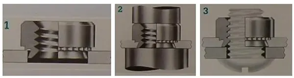
Punch holes in the flat surface of the metal part and then rivet on off-the-shelf mounting nuts.
It is best to use the hole diameter (d) recommended by the manufacturer for the mounting nuts.
However, it is important to note that riveting the nuts one by one is labor-intensive, time-consuming, and costly.
Therefore, almost all manufacturers use standard punch presses for this process.
If, unfortunately, a traditional punch press is used, there is a risk that the nuts may come loose.
This occurs because the punching speed of traditional punch presses is too fast;
The material of the workpiece does not have enough time to fully fill the grooves of the nut or the standoff before the punching cycle ends.
Visually, the problem is completely undetectable, but during final assembly, some nuts may come loose.
Therefore, it is best to select a machine capable of adjusting its punching speed for riveting the nuts.
Enclosure Assembly Positioning and Alignment
In the design of enclosure assemblies, there are often combinations of two parts, or three, four, or more parts that fit together.
Common fastening methods include screws, blind rivets, through-hole riveting, or spot welding.
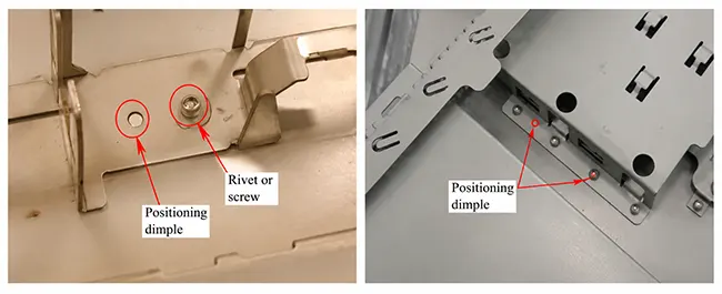
When spot welding, a spot welder must be used in conjunction with locating points, locating pins, or jigs to ensure correct positioning.
When using screws or blind rivets, since corresponding screw holes and blind rivet holes already exist, additional locating holes are often not added for alignment.
However, the diameters of screw holes and blind rivet holes are generally designed to be slightly larger to facilitate assembly.
Consequently, errors in the relative positioning of parts can easily occur.
In such cases, it is recommended to use positioning protrusions with minimal clearance for alignment.
When performing T/A Loop calculations, using positioning points with tighter tolerances as reference points also yields more accurate results.
Key Design Considerations for Sheet Metal Enclosures
Before creating a mold for an enclosure, it is best to first design the positions and sizes of the required labels.
You can mark the case in advance to facilitate alignment when applying the labels.
There are two most common marking methods:
1. Mark an “L” shape around the label’s perimeter, or on the top and bottom of the left side, or on the left and right sides of the top.
This method results in lower mold costs. However, since the label protrudes from the case surface, it is prone to scratches.
2. Increase the label’s dimensions by 0.3 mm. Create a 0.2–0.3 mm recess at the location where the label is to be applied.
Regardless of the method used, select one appropriate corner and apply a 45-degree chamfer.
Apply the same 45-degree chamfer to the corresponding position on the case.
This serves as a foolproof measure to prevent labels from being applied in different orientations at different times or by different staff members.

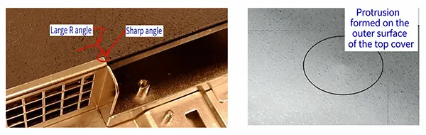
Avoid sharp corners at steps in the design. Be sure to incorporate large radii to prevent sharp corners from pressing against the top cover under heavy loads, which could cause bulging and affect the appearance.
In addition to increasing the case’s structural strength and securing the fan and air duct, the center panel can effectively prevent EMI if it makes proper contact with the inside of the top cover, significantly reducing the leakage of noise from the motherboard to the front.
Therefore, it is best to avoid placing plastic parts on the center panel, as this would block contact with the top cover.
Conclusion
In summary, effective sheet metal design is a delicate balance of functional requirements, manufacturing practicality, and cost efficiency.
The principles outlined—from maintaining minimum 1.5x material thickness for hole spacing and bend reliefs, to choosing hexagonal holes over square ones for die durability, to incorporating stiffening ribs and proper bend radii—all contribute to reducing production downtime, extending die life, and improving part quality.
Screw hole design demands careful consideration of material thickness and fastening method, while enclosure design must account for labeling, structural integrity, and EMI shielding.
By integrating these design considerations early in the development process, engineers can avoid costly rework, minimize production line stoppages, and deliver sheet metal products that are both robust and economical to manufacture.