
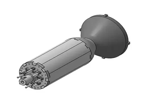





Thin-walled parts are widely used in the aerospace manufacturing sector due to their compact size, light weight, and high specific strength.
Nevertheless, such workpieces feature low deformation resistance.
Abnormal phenomena including deformation and chatter easily occur during turning and milling of internal and external surfaces.
These problems will result in the degradation of machining accuracy and surface quality.
Thin-walled components are susceptible to tool deflection subjected to cutting forces.
For the turning and milling of external contours of thin-walled parts, rationally designing an internal supporting device can boost structural rigidity and mitigate machining deformation.
This measure guarantees machining accuracy and further increases the yield rate of thin-walled components.
The grooved combustion chamber of a specific engine is a typical cylindrical thin-walled component.
Several rectangular cooling grooves are distributed uniformly along the longitudinal direction on the outer surface of the inner wall of the combustion chamber, which need to be machined by CNC milling.
The grooving process demands extremely high machining accuracy.
For typical cylindrical thin-walled parts such as combustion chambers, during the turning of the outer contour and the milling of rectangular grooves, a highly rigid, easily removable, and reliable internal support fixture must be installed within the part’s interior cavity.
This avoids situations where workpieces go out of machining tolerances or are even scrapped caused by insufficient rigidity of the internal supporting fixture.
Accordingly, the machining quality and production efficiency of thin-walled components can be greatly improved.
This paper takes a typical thin-walled combustion chamber as the subject of study and designs an internal support fixture for thin-walled parts that uses straight tapered and circular centers for positioning.
Operators clamp the fixture in a single setup to accomplish both external turning of the workpiece and milling of cooling channels, enabling high-quality and efficient machining of the combustion chamber.
Current State of Research
To date, scholars and researchers both in China and abroad have conducted extensive research on the issue of deformation during the machining of thin-walled components.
The German company IWN utilized the Inoex VL060 four-jaw chuck, independently developed by HWR Clamping Technology, to securely clamp an aluminum ring blank with precise clamping force without flattening it.
The aluminum ring has a diameter of 500 mm, a height of 320 mm, and a wall thickness of only 50 mm.
The multi-point clamping, internally supported, floating, self-centering hydraulic fixture designed by Song Yuyu features floating clamping and high self-centering accuracy.
It effectively minimizes workpiece deformation while accommodating internal support conditions where the inner surface roundness of thin-walled cylindrical castings is poor.
The double-conical surface internal support fixture for cylinder liners designed by Cheng Jinhui radially expands the outer cone sleeve to clamp sleeve-type products, offering high positioning accuracy and convenient clamping.
The aforementioned research on the machining of thin-walled cylindrical parts and their fixtures is ingenious and innovative, suitable for ring-shaped parts with high rigidity or small-diameter thin-walled cylindrical parts;
However, it is not suitable for thin-walled cylindrical parts with complex internal profiles or numerous external machining features.
This paper presents a design for an internal support fixture for thin-walled parts that uses straight-cone and circular mandrels for positioning.
It achieves internal clamping of the cylindrical section through eight evenly spaced support blocks that can radially extend and retract.
Engineers arrange rectangular slots and tenon structures at both ends for precise guidance, enabling the support blocks to extend and retract radially without constraint inside the rectangular slots.
Machinists clamp the workpiece in a single setup, and the fixture supports both outer surface turning and groove milling of the workpiece.
Thin-Walled Parts with Complex Internal Surfaces
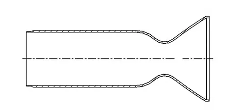
Figure 1 shows a schematic diagram of the external profile of a thin-walled part for a milled-groove combustion chamber.
The internal surface of this thin-walled part is machined using a CNC lathe after being clamped in a specific external mandrel fixture;
It serves as the machining reference for turning and milling the external surface.
Engineers identify prominent features of this thin-walled component: ultra-thin walls with a minimum thickness of merely 2 mm and a diameter-to-thickness ratio of 100:1.
It is a typical cylindrical thin-walled component.
The inner surface at the right end features a conical curved surface, while the inner surface at the left end consists of a long cylindrical section and a circular arc surface.
Localized tool clearance defects tend to arise during outer contour turning and external rectangular groove milling.
This makes it hard to guarantee the overall roundness of the workpiece.
Hence, great challenges are brought to machining and clamping processes.
Design of the Internal Support Fixture
Structural Components of the Internal Support Fixture
As shown in Figure 2, the internal support fixture primarily consists of a straight tapered mandrel, an arc-shaped tapered mandrel, a mandrel shaft, two conical frustums, eight support blocks, an extension sleeve, a positioning clamping plate, a trapezoidal nut, a sealing retaining ring, an O-ring, a tie rod, a pusher rod, a clamping plate, and screws.
The mandrel has center holes at both ends, which are used for centering with machine tool centers, respectively.
The straight taper sleeve of the fixture is a cast steel component, while the remaining structural parts are made of 45 steel.
The overall manufacturing cost is low, making it a cost-effective solution.
Feasibility Study and Analysis of an Internal Support Fixture
Figure 2(a) shows the internal support fixture in its expanded state.
When the trapezoidal nut is tightened, the straight tapered mandrel and arc-shaped tapered mandrel on the right end expand outward.
They brace the irregular surface on the right end of the thin-walled component, realize axial positioning, and support the machining of this irregular surface.
At the left end, the tie rod tightens the two conical frustums, causing the spreader block to expand radially and uniformly, thereby positioning and supporting the machining of the cylindrical surface.
Rectangular slots and tenons are machined at both ends of the spreader block.
These structures cooperate with the arc-shaped tapered mandrel and the positioning clamping plate.
The design ensures that the spreader block can move freely in the radial direction without jamming.
Figure 2(b) shows the internal support fixture in its retracted state:
The left-end pusher rod pushes apart the two conical frustums, causing the support block to retract radially and uniformly;
The right-end trapezoidal nut is loosened, separating the straight-cone mandrel from the arc-cone mandrel, allowing for rapid disassembly of the fixture components.
Figures 2(c) and 2(d) show sectional views of the fixture in the expanded and retracted states, respectively.
The clearance values of the support blocks are 0.8 mm and 0.11 mm, respectively, meeting the requirements for part machining and fixture disassembly.
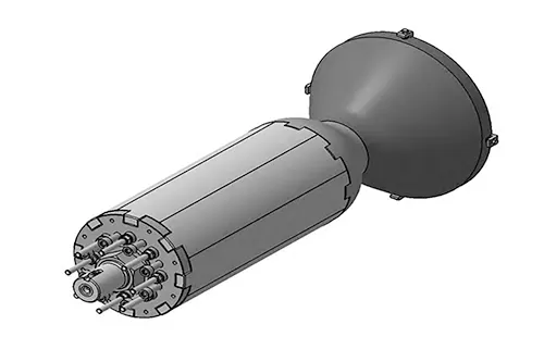
Figure 3 shows a 3D view of the internal support fixture.
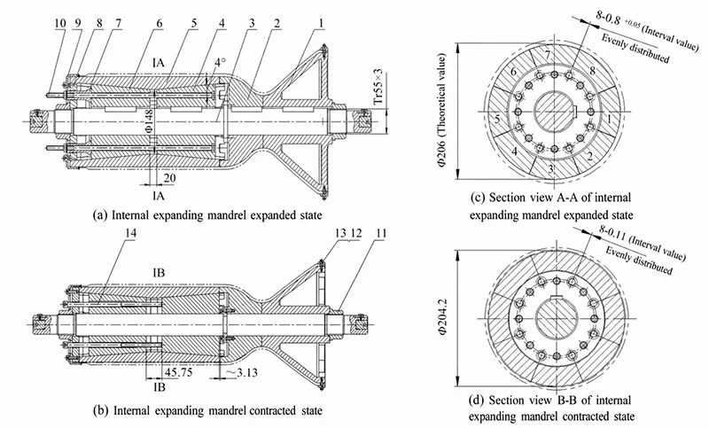
1—Straight cone tire; 2—Arc cone tire; 3—Mandrel; 4—Frustum I; 5—Support block; 6—Frustum II; 7—Extended sleeve; 8—Positioning pressure plate; 9—Sealing pressure ring; 10—Tie rod; 11—Trapezoidal nut; 12—Hex socket head cap screw; 13—Pressure plate; 14—Push rod
Key Geometric Parameters of the Internal Support Fixture
The inner diameter of the small end of the thin-walled part is (206 ± 0.05) mm;
Therefore, the theoretical outer diameter of the eight struts is set to 206 mm, with a gap of 0.8 mm between struts.
Designers adopt two conical frustums to realize wedge-driven expansion of the eight struts, and the radial expansion of struts varies linearly with the taper of the frustums.
1. Design Specifications and Boundary Conditions
Create boundary conditions:
1) After expansion, the outer diameter of the 8 struts is 206 mm, the gap between any two adjacent struts is 0.8 mm, and the spacing between the two conical frustums is 20 mm;
2) Engineers control the outer diameters of the eight struts within 204.4 mm after retraction, which creates a clearance of no less than 0.8 mm between the strut tops and the product inner wall and ensures smooth removal from the thin-walled component.
3) The clearance between any two adjacent struts after retraction is ≥0 mm.
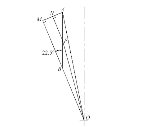
As shown in Figure 4, OM is the centerline between two adjacent struts.
Designers define Point A as the theoretical circular support position of the strut, Point B as the fully contracted position of the strut, and Point P as an arbitrary position in the contraction process.
Given that AM = 0.4 mm, OA = 103 mm, and ∠ABM = 22.5°.
2. Geometric Derivation and Parameter Calculation
In △ABM, based on boundary condition 1), the maximum radial contraction of the strut is:

After shrinkage, the minimum theoretical diameter of the 8 spacers is:

If the taper of a frustum is θ, the outer diameter is Φ, the axial displacement is L, and the radial displacement is L tan θ, the theoretical clearance between the support blocks is Δm = 2AM – 2L tan θ sin ∠ABM. Given that Δm = 0, find Lmax = 1. 045 cot θ.
In triangle POB, by the law of cosines, the maximum outer diameter of the support block after it contracts from A to P is 2OP, that is:

Equation (3) can be simplified to an equation relating Ltanθ to OP, namely:

The solution is:

The taper of the frustum is therefore:

In particular, 204.07 < 2OP < 206.0 < L < 1.045 cotθ.
Adding the boundary condition: Δm = 0.1 mm, we have OP = 204.2 mm.
Substituting this into Equations (5) and (6) and solving yields the following expressions for θ and L:

Taking into account the spatial layout of the internal support fixture, when L = 10–12 mm, θ = 4.72°–5.66°.
Here, an integer value of θ = 5° is taken as the taper angle of the conical frustum;
Thus, the axial displacement L required to complete the contraction of a single conical frustum is at least 11.33 mm.
Engineers determined the key geometric parameters of the internal support fixture for thin-walled parts via theoretical calculations, as listed in Table 1.
| Parameter | Value |
|---|---|
| Expansion block clearance (mm) | 0.8 |
| Maximum radial contraction of the expansion block (mm) | 1.045 |
| Distance between the two conical platforms (mm) | 20 |
| Axial displacement of a single conical platform, L (mm) | 11.33 |
| Conical platform taper angle, θ (°) | 5 |
Table 1. Key Geometric Parameters of the Internal Expanding Fixture
3. Machining Accuracy Control and Assembly Requirements
The machining accuracy of internal support fixtures is a critical factor in determining the quality of thin-walled products.
Machinists regard cutting heat generated in machining as a major inducement of thermal deformation in thin-walled parts, and this heat correlates closely with cutting parameters including cutting speed and feed rate.
During machining, the proper selection of cutting fluid ensures adequate cooling, effectively reduces thermal deformation of the parts, and improves machining accuracy.
The assembly process is particularly important for achieving the overall accuracy of the internal support fixture, especially regarding the tightening torque and sequence for the eight sets of tie rods and eight sets of push rods.
Process engineers formulate a rational process route, and operators strictly control tightening torque and tightening sequence to ensure uniform deformation of thin-walled parts and boost their machining accuracy.
Finite Element Simulation Analysis
This paper focuses on the relationship between the torque applied by the internal support fixture during the assembly process and the amount of support provided to the product.
Engineers simulate the assembly process via simulation software to acquire stress and deformation data of both the product and the internal support fixture.
It can provide accurate data support for the practical application of tooling and machining compensation within CNC programs.
Furthermore, it avoids the tool deflection phenomenon of thin-walled components.
Such phenomenon originates from inadequate internal supporting force offered by the fixture under cutting loads.
Load Conditions and Torque Calculation
Load Conditions: On the left side, the applied force is transmitted to 8 sets of support blocks via two conical frustums, thereby clamping the thin-walled part.
The tension force of the 8 tie rods (M12) is 30 kN × 8 = 240 kN; the clamping force of the 8 push rods (M12) is 20 kN × 8 = 160 kN.
On the right side, the straight-tapered and arc-tapered mandrels are clamped using trapezoidal nuts to brace the arched section of the thin-walled part;
The clamping force provided by the trapezoidal nuts (Tr55 × 3) is 300 kN.
The formula for calculating torque is:

In the equation: K is the torque coefficient, with a value of 0.15; F is the preload, in kN; d is the nominal diameter, in mm.
Therefore, the torque required for each tie rod is 54 N·m, and the torque required for each jack is 36 N·m.
Similarly, the torque required for the trapezoidal nut is 2,475 N·m.
Finite Element Simulation and Result Analysis
Engineers omit the bolts to simplify the finite element analysis model and apply the loads exerted by the two bolts on the large and small end faces of the conical frustum.
The trapezoidal nut was also omitted, and its force was applied to the large end face of the straight conical mandrel.
The finite element simulation diagrams of the internal support fixture, the thin-walled component, the 8 sets of external support blocks, and the 2 sets of conical frustums are shown in Figures 5 through 8.
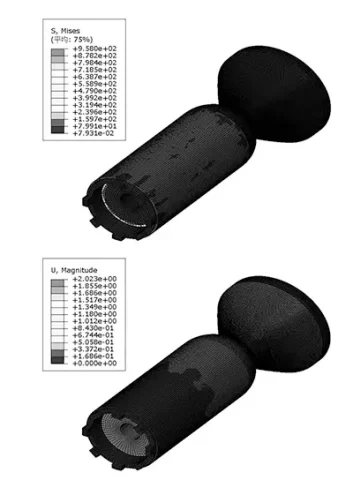
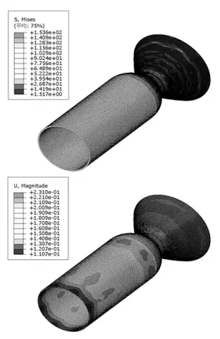
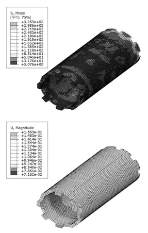
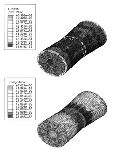
The analysis results show that, under the aforementioned loads, the maximum deformation in the curved section of the large end of the thin-walled part is 0.23 mm.
The maximum deformation in the straight section occurs near the junction between the straight section and the circular section;
The further away from the circular section, the smaller the deformation, decreasing roughly from 0.18 mm to 0.15 mm.
Machinists conduct compensatory machining along curved and straight directions during lathe machining of the thin-walled part’s outer contour to maintain consistent diameters of straight sections.
Engineers find that the maximum stress emerges at the fixture tip, forming a stress concentration zone;
Accordingly, machinists shall add chamfering features on the physical part during machining.
Engineering Application and Operational Guidance
Through simulation calculations, this paper obtains stress and deformation data for thin-walled parts, providing data support for subsequent CNC programming and assembly and tightening by operators.
Operators must strictly control the bolt tension and clamping forces to ensure the product’s yield rate and consistency.
Conclusion
The split conical-cylindrical internal support fixture investigated in this paper can effectively enhance the machining rigidity of thin-walled components.
It offers an internal support fixture solution for machining complex outer surfaces of thin-walled parts.
Finite element simulation analysis of the internal support fixture was conducted to quantitatively assess the impact of tie-rod tension and pusher-rod compression forces on the deformation of thin-walled parts.
This analysis guides process engineers in CNC programming and operators in controlling assembly tightening forces to ensure product yield and consistency.
Verified by practical production tests on site, the complete set of internal support fixture features convenient assembly and disassembly and favorable practical performance.
It greatly increases the qualified rate of products, and provides a reference solution for the production and machining of similar thin-walled components in workshops.