
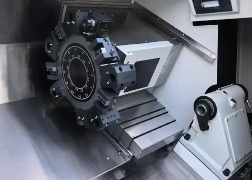





The B-axis tool holder is a core functional component that enables multi-process composite machining in turning-milling composite machining centers.
As the key load-bearing structure of the B-axis tool holder, the static and dynamic characteristics of the torque motor housing directly affect the tool holder’s motion accuracy, machining stability, and service life.
Machining technology is developing toward higher speed, higher precision and higher efficiency.
Against this background, the machinery manufacturing industry puts forward stricter requirements.
These requirements target the structural rigidity and anti-vibration performance of torque motor housings.
Finite element analysis serves as an effective research method.
It is used to investigate static and dynamic characteristics of mechanical structures.
This method has obtained extensive application.
It is widely adopted in the design and optimization of CNC machine tool core components.
Based on this, this paper focuses on the torque motor housing of the B-axis tool holder in a turning-milling composite machining center.
Finite element software was adopted in this research. A three-dimensional geometric model was built.
Static analysis and modal analysis were carried out subsequently.
The analysis reveals deformation characteristics and vibration properties under practical cutting conditions.
The research results offer references for structural design of similar parts.
Model Development and Stress Analysis of a Torque Motor Housing
During milling operations using the B-axis tool holder, the torque motor’s output power causes the electric spindle to perform a swinging motion.
The cutting loads generated by the cutting tool are transmitted to the machine bed through the torque motor housing.
Therefore, the torque motor housing of the B-axis tool holder serves as the primary component bearing the cutting loads.
Structural Overview and Parameter Basis
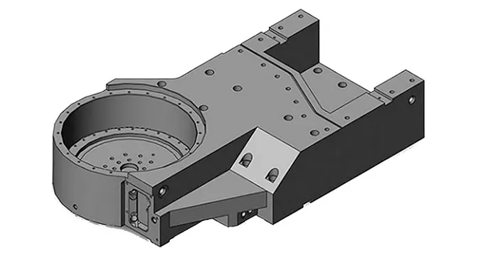
Its structure is shown in Figure 1, and the torque motor’s performance parameters are listed in Table 1.
The parameters of the torque motor are adopted for calculation.
The load values under extreme working conditions are solved.
These loads are decomposed along the X, Y and Z axes of the Cartesian coordinate system.
Load boundary conditions are accordingly defined for the follow-up finite element analysis.
| Item | Parameter |
|---|---|
| Rated power (kW) | 7 |
| Maximum torque (N·m) | 668 |
| Radius of the electric spindle rotation (mm) | 175 |
| Milling cutter extension length (mm) | 50 |
| Torque motor speed (r/min) | 15 (synchronized), 100 (independent) |
| Maximum electric spindle speed (r/min) | 12,000 |
Table 1. Torque Motor Parameters
Torque and Cutting Force Calculation
The formula for calculating torque is:

In the equation: T represents the torque of the torque motor; F represents the cutting force during the machining process;
R represents the lever arm length, which is equal to the sum of the rotational radius r of the electric spindle and the protrusion length l of the milling cutter.
Based on Equation (1), the cutting force during the machining process can be calculated to be approximately 2,969 N.
Cutting Force Decomposition and Boundary Conditions
The characteristics of the milling process are fully considered.
Empirical distribution ratios of cutting forces in high-speed machining are referenced.
The relational expressions among feed force F₁, vertical feed force F₂, transverse feed force F₃ and F are listed as follows:

Based on comprehensive process parameters, an appropriate scaling factor was selected to decompose the cutting forces in each direction into the X, Y, and Z axes of the global coordinate system.
The resulting forces acting on the torque motor housing were determined to be FX = 1,213 N, FY = 944 N, and FZ = 674 N.
Therefore, the forces acting on the torque motor housing along the X, Y, and Z axes are 1,213, 944, and 674 N, respectively.
Finite Element Model Development and Boundary Constraints
A 3D solid model of the torque motor housing was created in finite element analysis software.
The practical structural features of the housing are taken into consideration.
Local features including chamfers, fillets and holes below 10 mm in diameter are simplified.
This measure can raise computational efficiency while guaranteeing analysis precision.
The housing is made of 45 steel, with a Young’s modulus of 2.1 × 10⁵ MPa, a Poisson’s ratio of 0.269, and a density of 7.85 g·cm⁻³.
Automatic meshing was used to discretize the model, completing the construction of the finite element model.
The mesh size is 5 mm, the average element mass is 0.7, and the total number of elements is 175,526.
The entire bottom surface of the shell is fixed. Loads along the X and Z axes are applied to the inner wall of the circular hole at the bottom of the shell.
The load along the Y axis is applied to the plane containing the bottom circular hole.
The loads along the X, Y, and Z axes are set to 1,213, 944, and 674 N, respectively.
Static Characteristics Analysis
A finite element static analysis was performed on the torque motor housing to obtain the total deformation of the housing under cutting loads, as well as deformation contour plots in the X, Y, and Z axes, as shown in Figure 2.
As can be seen from Figure 2, except for the X-axis, the maximum deformation in all other directions is located near the inner wall of the motor shaft mounting hole in the housing.
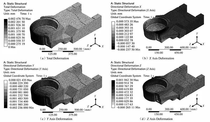
As shown in Table 2, the maximum displacement of the housing’s total deformation under cutting loads is 0.002 476 70 mm, which accounts for approximately 41.3% of the machine tool’s design machining accuracy of ±6 μm;
Therefore, it meets the machining accuracy requirements.
| Direction | Maximum Displacement (mm) |
|---|---|
| X-axis | 0.00057335 |
| Y-axis | 0.000021435 |
| Z-axis | 0.00106230 |
| Total deformation | 0.00247670 |
Table 2. Maximum Displacement of the Shell in Each Direction
Modal Analysis
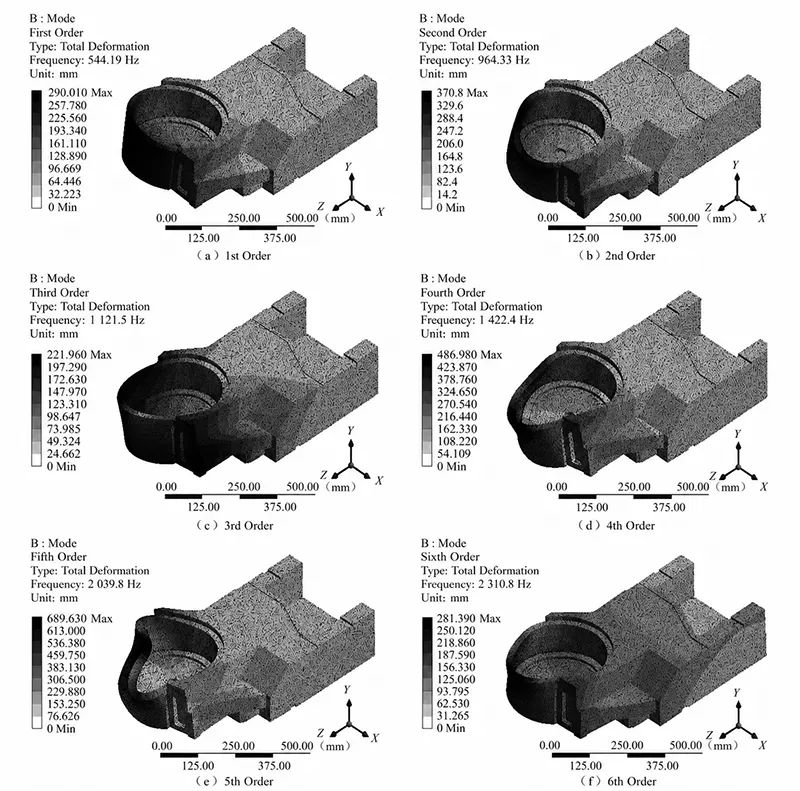
Under the same constraints as those used in the static analysis, a modal analysis was performed on the torque motor housing to determine the first six natural frequencies and corresponding mode shapes.
The modal frequency characteristics for the first six modes are shown in Figure 3, and the natural frequencies and principal mode shapes are described in Table 3.
The results in Figure 3 and Table 3 illustrate the vibration characteristics.
The main vibration modes corresponding to low natural frequencies are overall bending vibrations of the structure.
In contrast, medium and high natural frequencies are dominated by local vibrations.
| Mode | Natural Frequency (Hz) | Primary Vibration Mode |
|---|---|---|
| 1 | 544.19 | Overall low-frequency bending vibration |
| 2 | 964.33 | Local torsional–bending coupled vibration |
| 3 | 1,121.50 | Local vibration |
| 4 | 1,422.40 | Local vibration |
| 5 | 2,039.80 | Local vibration |
| 6 | 2,310.80 | Overall high-frequency vibration |
Table 3. First Six Natural Frequencies of the Shell
The first-order natural frequency is the lowest frequency naturally generated by a system when it vibrates, and it is one of the key parameters of its dynamic characteristics.
Equation (5) can be used for calculation. The critical minimum rotational speed triggering resonance of the torque motor is 32651 r·min⁻¹.
This value is much higher than the operating speeds of the torque motor and the electric spindle (see Table 1).
Since this speed is insufficient to induce resonance, the designed torque motor housing meets the design requirements.

In the equation: n is the rotational speed at which the motor resonates due to the torque; f is the natural frequency.
Conclusion
This research targets the torque motor housing belonging to the B-axis tool holder of a turn-milling machining center.
Operating load calculation, finite element model establishment, as well as static and dynamic characteristic analysis are accomplished in this paper.
Calculations show that the loads on the housing along the X, Y, and Z axes are 1,213, 944, and 674 N, respectively.
The maximum total deformation of the original housing under cutting loads is 0.002 476 70 mm, which meets machining accuracy requirements.
The first six natural frequencies are used to calculate the critical rotational speeds for resonance.
The minimum resonance rotational speed is markedly higher than the working speeds of the torque motor and the electric spindle.
Therefore, the structure meets actual operating requirements.