





Bending is a typical forming process for sheet metal workpieces. It comes with many prominent advantages. It can produce diverse and complicated part profiles.
Its processing speed is fast, and total energy consumption is low. In addition, the process is eco-friendly with comparatively low production costs.
Sheet metal parts have extensive application coverage in numerous industries.
Manufacturers apply them to produce general industrial equipment. Industries such as home appliances and kitchen cabinets also use them for consumer goods production.
Besides, special fields such as elevators and building curtain walls adopt sheet metal components as well.
CAD and CAM technologies have kept developing in recent years.
These technologies bring revolutionary transformations to sheet metal design and machining.
Workpieces with intricate outlines are bent more and more frequently in production. Such complex workpieces feature multiple flanges, large circular arcs and combined flanging structures.
Market requirements for processing equipment have greatly changed. In the past, users only needed basic processing machines.
Those old machines had simple structures and low machining accuracy. Now customers prefer fully automatic CNC equipment instead.
This new type of equipment delivers high precision and outstanding working efficiency.
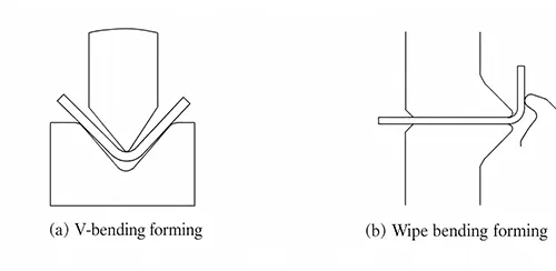
Traditional sheet metal fabrication generally uses press-type bending machines to perform edge folding on sheet metal (as shown in Figure 1a).
This passage explains how press-type edge folding works. The upper die, also called the punch, applies pressure to the sheet metal.
The sheet metal is compressed inside the cavity of the lower die. Compression force makes the sheet metal deform. This deformation finally shapes the folded edge of the part.
Edge folding refers to the sheet metal forming process in which the edges of a sheet are bent.
Traditional press-type bending follows a different working mode. The edge-bending forming process has a standout characteristic.
The workpiece performs rotation or horizontal translation during processing. Meanwhile, the die rotates or moves along the vertical direction.
This movement coordination supports both forward and reverse angle edge bending.
Operators do not need to flip the workpiece to complete different bending angles.
CNC edge-bending machines possess multiple obvious strengths. They achieve high processing efficiency and superior workpiece surface quality.
The equipment realizes a high level of automated operation. In addition, the machines save energy and cause little pollution.
It is also convenient for workers to adjust relevant parameters. They are ideal processing equipment for box-type parts and are widely used in industries such as elevators and home appliances.
Principles and Characteristics of the Flanging Process
Based on the operating principle of flanging, the motion path of the flanging die, instead of the die’s geometry, determines the bent shape of the workpiece;
Consequently, the functions of the dies on a flanging machine are relatively simple.
Manufacturers equip a flanging machine with three basic dies: upper clamping dies, lower clamping dies, and a flanging die.
The upper and lower clamping dies are primarily responsible for clamping and positioning the sheet metal, while the flanging die drives the motion and forming of the flange side.
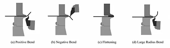
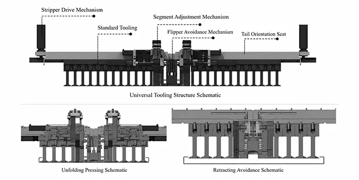
CNC sheet metal folding machines use a set of universal dies, as shown in Figure 2.
All movements are controlled by the CNC system. These machines can carry out several forming operations.
The operations include positive and negative angle folding. They also support large-radius arc folding and flattening.
Special-shape folding is another available function.
These capabilities let operators fold complex cross-section workpieces efficiently.
The application of CNC sheet metal folding machines achieves new breakthroughs in bending efficiency, process integration, and multi-process integration.
CNC sheet metal edge-bending machines eliminate the need for spatial flipping of workpieces or manual die changes.
With a short working stroke and fast feed rates, their overall efficiency exceeds that of manually operated press-bending machines by more than three times.
Current Status of Research and Development in Flanging Machines
CNC flanging machines come in two structural configurations: the rotary flanging type and the free-path type.
Flanging technology has achieved continuous progress. Different manufacturers follow independent research and development routes.
They develop customized functional parts matching diverse working conditions. These parts include dies, flanging devices and clamping devices.
The whole industry is evolving toward high-precision and high-efficiency automated production.
Structural Principle & Application of Rotary CNC Flanging Machines
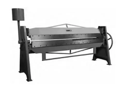
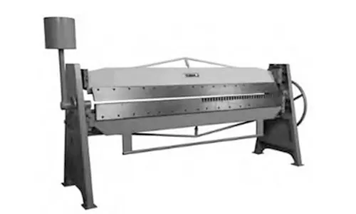
Rotary CNC flanging machines evolved from traditional manual flanging machines and consist primarily of a frame, a clamping device, and a flanging device (see Figure 3).
Here is how these machines operate. The clamping beam moves vertically up and down.
This movement secures the sheet metal tightly. At the same time, the flanging beam and its matching die revolve around a fixed shaft.
The rotation exerts force on the free edge of the sheet metal.
This force bends and deforms the sheet metal edge, ultimately forming a finished flange shape.
Well-known brands on the international market include RAS and Schroder (Figure 4).
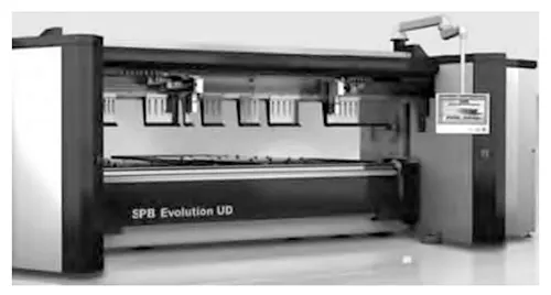
Technical Advantages and Product Layout of Free-Trajectory Flanging Equipment
The trajectory-type bending machine has a core structural feature. Its bending beam is capable of two types of movement inside the bending zone.
The two movement directions are horizontal and vertical.
The beam can carry out these two motions separately. It can also move along both directions at the same time.
This type of CNC bending machine can define arbitrary bending trajectories, enabling not only large arcs and flattening functions but also complex bending operations.
Italian company Salvagnini first successfully developed the free-trajectory bending machine in 1977.
After more than 40 years of in-depth research and technical improvements, it has become a leader in the development of CNC sheet metal bending equipment.
Salvagnini bending centers utilize adjustable universal dies and upper and lower bending blades, offering strong adaptability to different workpieces;
The Automatic Die Adjustment (ALA) function eliminates waiting time; a single-positioning, high-precision, and multifunctional feeder that saves time;
An advanced graphical CNC system capable of automatically sequencing complex bending processes;
And a wide variety of configuration options that facilitate integration into flexible manufacturing systems (FMS) combining punching, shearing, and bending.
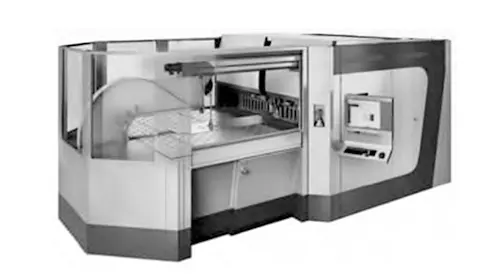
Salvagni-ni has successively launched bending machines with different functionalities, including the P4Xe, P2Xe, P2lean (as shown in Figure 5), and P1lean.
By segmenting the market based on demand, Salvagnini has developed a range of flanging machines that are highly competitive in terms of performance and price.
Current Technical Development Bottlenecks of Flanging Equipment
Great progress has been made in servo and CNC technologies over roughly the last ten years.
Relevant control technologies have also kept evolving alongside them.
Even so, many original forming technologies can no longer satisfy today’s market demands.
Development of Yawell Edge Bending Machines: Scope and Key Achievements
Yawell Machine Tool keeps up with global development trends of sheet metal processing equipment.
The enterprise has independently developed a full series of edge bending machines.
These new machines make important breakthroughs in three key performance indicators.
The indicators are machining precision, operational flexibility and structural high rigidity.
Innovative Structural Design
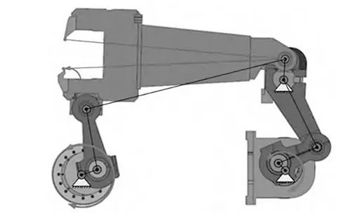
During the R&D process, the company achieved several breakthroughs in structural design, including the design of edge bending mechanisms, automatic die design, and the development of flexible units.
1. High-Rigidity Bending Mechanism and Dedicated Control System
This equipment adopts a bending mechanism with high transmission rigidity.
Machines need to realize several core bending functions. They must support both positive-angle and negative-angle bending.
They also need flexible switching of bending directions. Engineers design two key structures to meet all these functional requirements.
One is a high-rigidity machine frame. The other is a multi-link bending mechanism featuring strong transmission rigidity.
Engineers have developed a dedicated control system for the equipment.
This system contains multiple core modules. They cover the bending trajectory model, three-axis coordinated control, and motion control system.
When matched with the mechanical structure, the system can control the tips of bending dies.
The die tips can follow all kinds of preset bending paths according to processing requirements.
This function realizes fully automatic machining for box-shaped sheet metal parts.
2. Fully Automatic Mold Assembly Device.
Researchers developed a clutch-type automatic mold assembly system.
This machine is equipped with a rotary insert mold featuring a self-assembling structure.
It supports automatic mold assembly in 5-millimeter unit increments.
This design allows operators to quickly switch between different mold lengths.
As a result, the equipment can process workpieces of various dimensions.
An intermediate clearance mechanism enables controlled retraction of the mold to accommodate clearance during multi-sided folding, as shown in Figure 7.
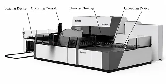
3. Development of a Flexible Automation Unit.
Researchers carried out targeted studies on multiple core components of the folding machine.
These components cover feeding, suction, clamping and alignment units.
They also include conveying, rotation and unloading mechanisms.
The research aims to realize efficient handling and transportation of workpieces.
Operators can complete the entire folding process fully automatically in the end.
The flexible automation unit is shown in Figure 8.
Research and Breakthroughs in Key Core Technologies
We first finished the development of prototype machines.
Based on these prototypes, we carried out a great many R&D tasks.
The research covers several key technical directions. They include structural rigidity optimization and production efficiency optimization.
We also conducted research to improve overall machining precision.
We have achieved breakthroughs in several key core technologies, resulting in significant improvements in all technical performance metrics.
1. High-Rigidity Technology for Key Components.
We carried out structural upgrades and optimization on several key components.
The main optimized parts include the machine frame and bending beams.
These improvements raise the overall rigidity of the bending machine’s main body structure.
This high structural rigidity keeps stable dimensional precision between upper and lower dies.
The precision stays consistent throughout the entire bending operation.
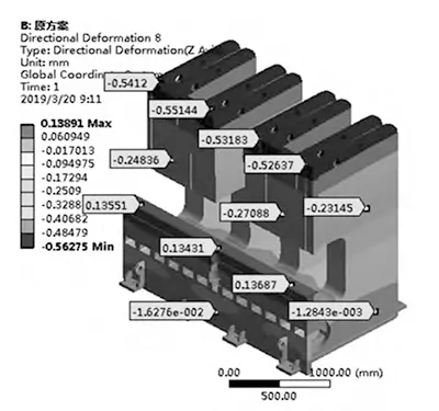
We optimized the distribution mode of clamping force. We also moderately added more force application points.
These adjustments make the clamping force between dies much more uniform.
It restrains uneven deformation of the die set in bending operations.
Meanwhile, product reject rates caused by such deformation are reduced. The above effect can be seen in Figure 9.
2. Precision Manufacturing Process Technology.
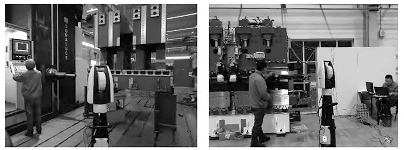
This section focuses on the machining process research of precision parts. Workers apply special precision optical measuring instruments during production.
Typical equipment includes laser position trackers and interferometers. These instruments conduct real-time measurement throughout the machining process.
Measured data is used to compensate for errors of the machining equipment.
The compensation technology supports the fabrication of precision-level components.
Figure 10 shows the relevant measurement scenario.
Development of Machining and Assembly Fixtures:
We have achieved the machining and manufacturing of precision-grade components such as molds, frames, and flanged beams;
Researched specialized testing and debugging fixtures;
And designed and developed various machining fixtures and debugging/measuring fixtures.
At the same time, we have established assembly and testing specifications to improve component assembly accuracy and shorten assembly cycles.
3. Technologies for Improving Transmission Accuracy and Structural Optimization of Linkage Mechanisms.
Structural Optimization: Control transmission clearance and optimize transmission stiffness.
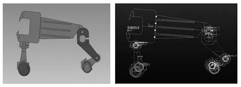
We identified and analyzed the primary factors affecting dynamic precision after conducting in-depth research on the flanging link mechanism and running dynamic simulations on a digital platform.
We optimized the precision and performance of the parallel mechanism segment inside the flanging mechanism to realize synchronization in the flanging area.
We simultaneously optimized assembly deviations to attain stable, reliable positioning accuracy, as shown in Figure 11.
4. High-Speed Flanging Technology.
We optimized the structure of the flanging beam and link components to reduce the inertia of moving parts and boost dynamic performance.
We analyzed the characteristics of the flanging link mechanism during the flanging process and obtained an optimal mechanism solution by optimizing the link parameters.
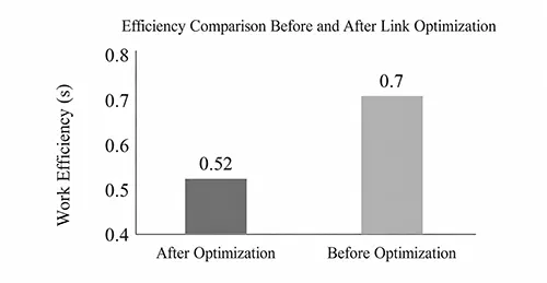
By optimizing the efficiency of multi-axis coordinated motion control in the control system, the single-step flanging trajectory time was reduced from 0.7 s to 0.52 s, enabling high-speed flanging. As shown in Figure 12.
5. Research and Optimization of High-Speed Parallel Technology.
Through efficiency analysis and optimization of the entire flanging process, we developed a multi-axis parallel control system based on the workpiece’s spatial position model and safe operating zone.
Combined with optimization of the feed axis and the parallelization of operations across each process step, this system achieves a processing time of ≤33 seconds for typical workpieces.
6. Technology for High-Quality Bending Surfaces.
Starting from the mechanism of sheet metal bending deformation, we utilized a digital simulation platform to analyze changes in material flow, stress distribution, and other state and shape variations during large-deformation processes.
We built a detailed relational model. This model describes displacement and friction between sheet metal and die tips.
We revised and upgraded the trajectory equations used in rolling bending.
The link control model was further optimized accordingly.
We also fine-tuned relevant control parameters. All these measures together produce scratch-free surfaces after bending.
Process Research Results
We studied multiple bending technologies from the process perspective.
These technologies can realize several special forming processes.
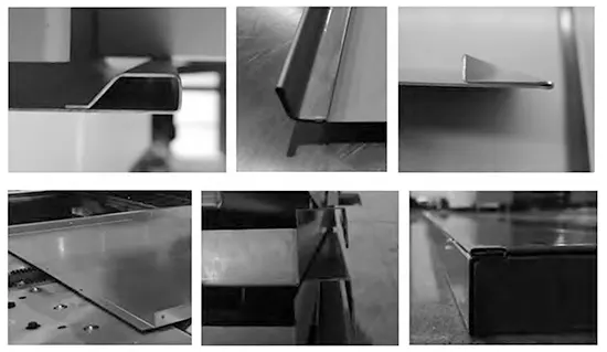
They include closed-end bending, flanging after flattening, and flattening of flanged beams.
Rich process types allow the equipment to match diverse industrial application scenarios.
The finished formed workpieces are presented in Figure 13.
Conclusion
(1) CNC folding machines utilize universal dies and free-trajectory folding technology to perform a variety of processes, including positive and negative angle folding, large arcs, and flattening.
Their overall efficiency can reach more than three times that of traditional press-bending machines.
(2) Yawell folding machines have made several core technological breakthroughs.
These breakthroughs cover four key technical modules.
They are high-rigidity frame design, fully automatic die-changing system, flexible automation units, and multi-axis parallel control.
Thanks to these technologies, the equipment sees remarkable upgrades in three core performances.
The upgraded indicators are machining precision, production efficiency and workpiece surface quality.
(3) The sheet metal market currently has robust market demand. CNC folding machines possess many outstanding advantages.
They feature high processing efficiency and excellent machining precision.
The equipment also delivers a high level of automation. In addition, it is energy-saving and environmentally friendly.
Making full use of these strengths will promote industrial transformation.
It will further accelerate the overall upgrading of the sheet metal industry.