

China CNC Milling » Blog » Machining Process Specification Development: Complete Steps, Principles & Practical Case
FAQ
What materials can you work with in CNC machining?
We work with a wide range of materials including aluminum, stainless steel, brass, copper, titanium, plastics (e.g., POM, ABS, PTFE), and specialty alloys. If you have specific material requirements, our team can advise the best option for your application.
What industries do you serve with your CNC machining services?
Our CNC machining services cater to a variety of industries including aerospace, automotive, medical, electronics, robotics, and industrial equipment manufacturing. We also support rapid prototyping and custom low-volume production.
What tolerances can you achieve with CNC machining?
We typically achieve tolerances of ±0.005 mm (±0.0002 inches) depending on the part geometry and material. For tighter tolerances, please provide detailed drawings or consult our engineering team.
What is your typical lead time for CNC machining projects?
Standard lead times range from 3 to 10 business days, depending on part complexity, quantity, and material availability. Expedited production is available upon request.
Can you provide custom CNC prototypes and low-volume production?
Can you provide custom CNC prototypes and low-volume production?
Hot Posts




Processing techniques are the lifeblood of machining; 90% of quality issues stem from the process design phase.
The reality at many machining shops is that process engineers, after reviewing drawings, rely solely on experience to write programs and set parameters without conducting systematic process analysis or design planning.
As a result, problems frequently arise during machining—such as improper clamping, inconsistent reference points, unscientific sequence planning, and incorrect tool selection—which ultimately require on-site “firefighting” to remedy.
The preparation of process specifications serves as the bridge between drawings and machining.
A well-crafted set of process specifications ensures a smooth, efficient machining process with consistent quality;
A poorly drafted set, however, can plunge the entire shop floor into chaos.
Today, we will systematically break down the complete process of preparing process specifications:
From part drawing analysis, blank selection, and reference point determination to operation sequencing and the drafting of process documents, providing practical methods and examples for each step.
Basic Process for Developing Manufacturing Instructions
Simply put, developing manufacturing instructions involves converting the requirements specified in a part drawing into executable machining steps.
The complete process includes:
Step 1: Analyze the part drawing and product assembly drawing to clarify the part’s function, structural characteristics, and technical requirements.
Step 2: Determine the production type (single-piece, small-batch, or mass production) and select the blank type and manufacturing method.
Step 3: Determine the machining reference points and clamping plan.
Step 4: Develop the process sequence—organizing the operations in order.
Step 5: Determine the machining content, equipment, fixtures, cutting tools, and cutting parameters for each operation.
Step 6: Prepare process documentation (process cards, operation cards, and inspection cards).
Step 7: Conduct a joint review and approval, proceed to trial production for verification, and finalize the process after optimization.
Many process engineers only perform steps four through six, neglecting the analytical work involved in the first three steps.
However, it is precisely these first three steps that determine the correctness and cost-effectiveness of the process.
Parts Drawing Analysis: The Foundation of Process Design
When you receive a parts drawing, don’t rush to write up the process; first, spend half an hour thoroughly studying the drawing.
Structural Analysis
What geometric features make up the part? What machined surfaces does it have?
What are the relationships between these surfaces? Are there any special features such as thin walls, deep holes, grooves, or threads?
Structural analysis determines which surfaces require machining and how to machine them.
For example, a shaft-type part with a flange may require multiple machining operations, such as turning the outer diameter, turning the end face, threading, drilling, and milling a keyway.
Analysis of Technical Requirements
Focus on the dimensional tolerances, geometric tolerances, surface roughness, materials, and heat treatment requirements specified in the drawings.
The dimensional tolerance grade directly determines the choice of machining method.
For rough-machined holes with a tolerance grade of IT12 or lower, a single drilling operation is sufficient;
For precision holes with an IT7 tolerance grade, drilling, reaming, tapping, or boring is required.
Geometric tolerances are sometimes more critical than dimensional tolerances.
For example, a hole with a positional tolerance requirement of φ0.05 mm requires operators to use precision fixtures for clamping and machine the reference surfaces first.
Neglecting geometric tolerances can create quality problems: parts may meet dimensional specifications, yet assemblers cannot fit them together.
The material and heat treatment determine the tool material, cutting parameters, and process sequence.
For example, 45 steel, after quenching and tempering, has a hardness of HRC 28–32 and offers good machinability;
If the material is changed to Cr12MoV hardened to HRC 60, CBN tools must be used for turning.
Process planners should schedule the heat treatment process between rough machining and finish machining to eliminate heat-induced deformation.
Reference Analysis
Analyze the design references, process references, and measurement references on the drawings.
Strive to follow the “principle of unified references”—ensuring that design, process, and measurement references are consistent—to avoid errors caused by reference conversions.
For example, the design reference for a stepped shaft is the axis of the center holes at both ends.
During turning, operators clamp the workpiece between two centers and use the center holes as the positioning reference.
This ensures that the outer circles of each section are coaxial with the shaft axis, meeting the drawing requirements.
If, instead, one end is clamped in a chuck and the other end is held by a center, the reference changes, which may result in coaxiality exceeding the tolerance.
Blank Selection: Determines Material Utilization and Machining Allowance
The type of blank directly affects machining costs and quality.
Common types of blanks include: profiles (round bars, square bars), forgings, castings, and welded parts.
Shaped Stock
Cutting round or square bar stock directly is the simplest method for producing blanks.
It is suitable for parts with simple structures, such as shafts and discs, that do not have large diameters.
Material utilization is low (approximately 50% to 70%), and machining allowances are large; however, this method offers low costs and short lead times.
Forgings
Forging alters the internal microstructure of the material, aligning the fiber orientation along the part’s contour, thereby enhancing the part’s strength and reliability.
Forgings are suitable for shafts, gears, connecting rods, and other components that are subject to high loads and have complex shapes.
Although forgings are more expensive than extruded profiles, they offer higher material utilization and require less machining time.
Castings
Suitable for complex structural parts such as housings, casings, and brackets.
Cast iron parts offer good vibration damping and wear resistance at a low cost.
Casting blanks carry large material allowances and may contain casting defects, so process planners must schedule aging or annealing treatment.
Welded Parts
Suitable for large-scale frame and base components.
These parts are formed by welding steel plates and profiles, offering high flexibility and short production cycles.
However, they are prone to welding distortion and residual stresses, requiring stress-relief annealing and machining after welding.
Common Misconceptions in Blank Selection:
When selecting a blank, some consider only the cost of purchasing the blank itself, without factoring in subsequent machining costs.
For example, when machining a stepped shaft directly from large-diameter round bar—although the round bar is inexpensive—it requires a large amount of material removal, results in significant tool wear, and takes a long time to machine.
If manufacturers adopt a forged blank instead, even though the blank costs slightly more, they greatly cut machining time and actually lower total overall cost.
Reference Selection and Clamping Solutions: The Core of the Process Plan
Principles for Selecting a Rough Reference
The reference used in the first machining operation is the rough reference, i.e., the unmachined surface of the blank. Selection principles:
Select important surfaces as rough references—surfaces requiring uniform machining allowances should be chosen as rough references.
For example, when machining machine bed guideways, use the guideway surface as the rough reference to machine the bottom plane, and then use the bottom plane for positioning when machining the guideway surface to ensure uniform machining allowances on the guideway surface.
Select smooth and flat surfaces as rough reference surfaces. Avoid uneven regions on the blank such as flash and gates.
Process engineers may use rough reference surfaces only once. Because these surfaces belong to the raw blank, repeated use introduces substantial positioning errors.
Subsequent operations should use machined surfaces as fine reference surfaces.
Principles for Selecting Precision Reference Surfaces
We regard machined surfaces adopted for locating references as precision reference surfaces.
Selection principles:
“Reference Coincidence” Principle: Whenever possible, align the locating reference with the design reference to avoid errors caused by misalignment.
For example, when designers dimension the position of a hole on a part drawing with the bottom surface as the design reference, operators machine the hole with the bottom surface as the locating reference during clamping instead of using a side surface.
“Unified Reference” Principle: During the machining process, use the same locating reference as much as possible to machine all critical surfaces, ensuring the positional accuracy of each surface.
For example, using the center holes at both ends uniformly for locating shaft-type parts ensures the coaxiality of the outer circles in each section.
“Surface-as-Reference” Principle: In certain finishing operations (such as honing and lapping), the surface being machined itself serves as the locating reference to achieve extremely high surface accuracy.
Common Clamping Methods
Shaft-type parts: Two-center clamping, chuck clamping, and one-clamp-one-center clamping.
Disc-and-sleeve-type parts: Chuck clamping, mandrel clamping, and flange clamping.
Housing-type parts: Vise clamping, clamping plate bolts, special fixtures, and zero-point quick-change pallets.
When selecting a clamping method, it is important to balance positioning accuracy, clamping reliability, and operational efficiency.
For high-volume production, manufacturers use specialized fixtures;
For small-batch, high-variety production, they adopt modular or universal fixtures together with alignment procedures.
Developing a Process Route: The Key Logic Behind Sequencing Operations
The process route serves as the backbone of the process specifications.
A reasonable sequence ensures smooth processing; an unreasonable sequence, however, can lead to overall problems even if each individual operation is flawless.
Stages of Machining
Process planners typically split the machining process for high-precision parts into three stages: rough machining, semi-finishing, and finishing.
Rough Machining Stage: Removes the majority of the machining allowance.
The goal is high efficiency, and precision requirements are not high.
Rough machining generates significant cutting heat and residual stress, providing a blank for subsequent finishing operations.
Semi-Finishing Stage: Eliminates deformation caused by rough machining, achieves a certain level of precision, and prepares the workpiece for finishing.
Finishing Stage: Meets the final drawing specifications.
Finishing involves a small amount of material removal and low cutting forces, resulting in minimal deformation and ensuring dimensional accuracy and surface quality.
Benefits of Staging: Allows for the rational use of machinery with different precision levels (older machines for rough machining, high-precision machines for finishing);
Enables the scheduling of stress-relief treatment after rough machining; and prevents thermal deformation from rough machining from affecting finishing accuracy.
Basic Principles of Process Sequencing
Reference surfaces first, then others: The first operation should be to machine the precision reference surfaces.
For example, for shaft-type parts, drill the center hole first; for housing parts, machine the bottom surface and locating pin holes first.
Rough machining before finish machining: Perform rough machining first, followed by finish machining, to ensure uniform finish machining allowances.
Prioritize Primary Over Secondary: Process planners prioritize primary surfaces (fitting surfaces, working surfaces) in the machining sequence and machine secondary surfaces (bolt holes, oil grooves, etc.) in between.
Machine surfaces before holes: For housing-type parts, machine flat surfaces before drilling holes.
Because flat surfaces have a large area and provide stable positioning, the machined surfaces can serve as locating references for subsequent hole machining.
Scheduling of Heat Treatment Operations: Process planners arrange annealing and normalizing after blank fabrication;
They schedule quenching and tempering after rough machining and before finish machining;
They perform low-temperature aging after semi-finish machining; and they carry out surface hardening before final finish machining.
Process Consolidation and Decentralization
Process Consolidation: Completing as many machining operations as possible on a single machine tool.
CNC machining centers and turn-mill combination machines are typical examples of process consolidation.
Advantages: Reduces the number of setups, shortens non-cutting time, and ensures positional accuracy;
Disadvantages: High equipment costs and high demands on programming and maintenance.
Process Decentralization: Distributing machining operations across multiple machine tools.
This approach is commonly used in traditional conventional machine tool workshops.
Advantages: Low equipment costs, relatively low skill requirements for operators, and high production flexibility;
Disadvantages: Frequent setups and long turnaround times.
Modern manufacturing tends toward process centralization, particularly for the single-setup, multi-operation machining of complex parts.
Process Step Design: Equipment, Cutting Tools, and Cutting Parameters
Once the process sequence has been determined, detailed machining parameters must be established for each process step.
Equipment Selection
Select the appropriate machine tool based on the part’s machining requirements, dimensions, production volume, and available equipment resources.
Principles: Machining accuracy must match the machine tool’s accuracy;
The part dimensions must fall within the machine tool’s machining range; and the production cycle must align with the production volume.
Tool Selection
Select tools based on the type of surface to be machined, the material, and the nature of the machining operation.
For example: use a cylindrical turning tool for external cylindrical machining;
Use a drill, reamer, or boring bar for hole machining; and use a face mill or end mill for flat surface machining.
Select cutting tool materials based on the workpiece material: use carbide-coated inserts for ordinary steel parts;
Use specialized PVD coatings for stainless steel and titanium alloys; use CBN tools for hardened steel; and use Class K carbide for cast iron.
Determining Cutting Parameters
Principles for selecting cutting speed, cutting depth, and feed rate:
Rough machining prioritizes efficiency, so use a larger cutting depth and feed rate while appropriately reducing the speed;
Finish machining prioritizes quality, so use a smaller cutting depth and feed rate while appropriately increasing the speed.
Cutting parameters can be based on the initial values recommended in tool catalogs, which should then be adjusted according to actual conditions.
Each workshop should build its own database of cutting parameters and gradually establish standards.
Preparing Process Documents: Putting Processes on Paper
Process documents serve as the basis for guiding on-site production and must be clear, complete, and actionable.
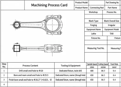
Process Card
This document outlines the entire machining process for a part, listing the sequence number, name, description, equipment, and tooling for each process step.
It serves as the basis for production scheduling and technical preparation.
Process Card
Provides detailed instructions for each process step, including: a simplified process diagram (showing dimensional tolerances and technical requirements for the machined surfaces in that step), clamping methods, positioning references, cutting tools, measuring tools, cutting parameters, and inspection requirements.
The process card serves as the most direct operational guide for operators.
Inspection Sheet
Specify the inspection items, inspection methods, inspection tools, and acceptance criteria for each process.
Important dimensional and geometric tolerances must be clearly indicated.
On-Site Management of Process Documents
Process documents should be placed next to the machine tool or on a digital terminal so that operators can access them at any time.
Any process changes must follow the formal procedure, including issuing a process change notice and collecting the old documents to prevent misuse.
Process Validation and Continuous Optimization
Process specifications are not set in stone once finalized. During initial production, process engineers must work alongside the production line to observe actual machining conditions and document any issues.
If improper clamping, inappropriate parameters, or incorrect tool selection are identified, the process documentation should be revised promptly.
After mass production begins, statistical process control data is used to monitor process stability.
If the Cpk for a particular process step remains consistently low, the cause should be analyzed and the process optimized.
Areas for continuous process optimization include: reducing the number of process steps, improving machining efficiency, lowering tooling costs, and enhancing quality stability.
Case Study: Developing a Process Specification for a Flange Part
Taking a typical flange part as an example, the material is Q235 steel, with a production batch of 200 pieces.
Drawing specifications: Outer diameter φ120 mm, inner bore φ60 H8, thickness 20 mm, parallelism of both end faces 0.03 mm, coaxiality between the inner bore and the φ80 mm outer diameter φ0.05 mm, surface roughness Ra 3.2 μm.
Process Analysis
The part has a simple structure, with the main machined surfaces being the end faces, the internal bore, and the external diameter.
The precision requirements are moderate and can be met using a standard-precision CNC lathe.
To meet the φ0.05 mm coaxiality requirement, the internal bore and φ80 external cylinder must be machined in a single setup to avoid errors caused by repeated setups.
To meet the 0.03 mm parallelism requirement between the two end faces, both faces must be turned in a single setup, or one end must be machined first and then used as a reference to machine the other end.
Process Flow
Step 10: Cutting to size, round bar φ125 × 22 mm.
Step 20: Conventional lathe—clamp the outer diameter, rough-turn the end face, rough-turn the inner bore to φ57 mm, and rough-turn the outer diameter to φ122 mm.
Step 30: Heat treatment—stress-relief annealing.
Process 40: CNC turning—clamped by the rough-turned outer diameter; finish-turn the end face; finish-turn the outer diameter to φ120 mm and φ80 mm; finish-turn the bore to φ60H8; chamfer.
Completed in a single setup to ensure coaxiality.
Process 50: Fitting—deburring.
Process 60: Inspection.
Key Process Points
After rough machining, perform stress-relief annealing to eliminate internal stresses generated during rough turning and prevent deformation after finish machining.
Finish machining is completed in a single setup on a CNC lathe to ensure coaxiality and parallelism.
Inspect the part using a micrometer, an inside micrometer, and a roughness tester.
This case study illustrates that even for simple parts, process design requires careful consideration.
The core approach to ensuring quality involves appropriately dividing rough and finish machining, correctly scheduling heat treatment, and selecting a single-setup machining plan.
Summary
Developing a machining procedure is a systematic process that begins with the analysis of part drawings and involves making decisions step by step.
Many machining shops prioritize “programming” over “process,” treating programmers as process engineers; however, programming is actually only one part of the process.
A comprehensive machining procedure should clearly address the following: what raw material to use, in what order, on what equipment, with what cutting tools, using what parameters, how to set up the workpiece, and how to inspect it.
Only by thoroughly considering these issues in advance can we avoid on-site chaos and the chaotic practice of “modifying the process while machining.”
It is recommended that every factory establish a process review system; process specifications for critical parts should undergo a multi-person review to pool ideas and minimize errors.
If you encounter specific challenges during the process specification development, please feel free to describe your part type, material, precision requirements, and current process route in the comments section, and we can work together to analyze opportunities for optimization.