
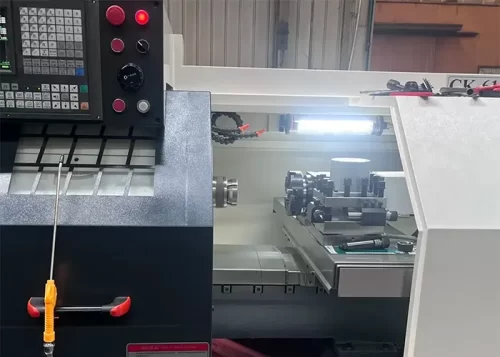





Complex parts such as aircraft engine blades, precision mold cavities, and medical implants are generally characterized by irregular shapes, high precision requirements, and difficult-to-machine materials.
These characteristics place higher demands on the rigidity, precision, and level of intelligence of CNC lathes, and traditional CNC lathes are no longer sufficient to meet these machining needs.
The machining process also faces technical challenges such as vibration control, thermal deformation suppression, and toolpath planning.
This article carries out a systematic research on several key technologies.
The research covers bed structure optimization, high-performance spindle development, and intelligent control algorithm integration.
It aims to greatly improve the machining performance of CNC lathes.
This provides solid technical support for the domestic production of China’s high-end manufacturing equipment.
It also promotes the high-precision, high-efficiency, and intelligent development of CNC machine tools.
Analysis of Technical Requirements for Machining Complex Parts on CNC Lathes
Complex components for aerospace, precision mold, and medical device industries feature irregular geometries and stringent precision requirements.
For example, the twist angle of a typical aircraft engine blade can exceed 45°, with a wall thickness of only 1.5–3 mm and geometric and positional tolerances requiring IT5–IT6 grades.
The radius of curvature for the cavity surfaces of precision molds ranges from 0.5 to 50 mm, and surface roughness must be within Ra 0.4–0.8 μm.
During machining, these parts present challenges such as significant fluctuations in cutting forces, sensitivity to thermal deformation, and complex toolpaths;
CNC lathes must meet performance specifications such as static stiffness ≥ 800 N/μm, spindle radial runout ≤ 0.003 mm, and positioning accuracy of ±0.005 mm to ensure stable machining quality.
Traditional CNC lathes have significant shortcomings in bed stiffness, spindle accuracy, and control response, making it difficult for them to meet the high-precision machining requirements of complex parts.
Optimized Design of Core Manufacturing Technologies for CNC Lathes
Design and Optimization of High-Rigidity Bed Structures
1. Topological Optimization Design and Finite Element Analysis of the Bed
As the fundamental supporting component of a CNC lathe, the bed’s stiffness characteristics directly affect machining accuracy.
Designers use topology optimization methods to lightweight the bed, realizing optimal material distribution while satisfying stiffness requirements.
They build a 3D finite element model for the bed and apply a maximum spindle cutting force of 6,000 N together with guideway constraints.
A static analysis is then performed using ANSYS software, with the optimization objective function defined as:

In the equation, C represents flexibility, F represents the load vector, and u represents the displacement vector.
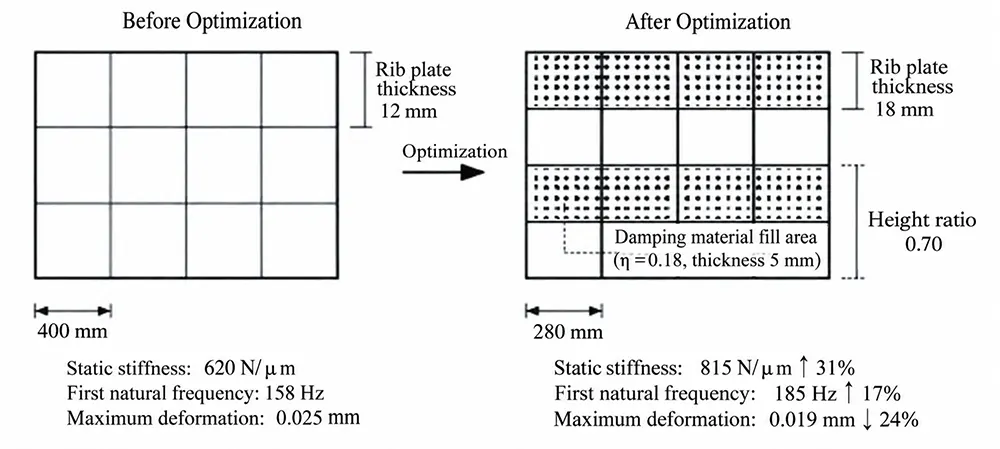
After 15 optimization iterations, the optimization scheme cut the bed mass by 18%, lowered maximum deflection from 0.025 mm to 0.019 mm, and raised static stiffness from 620 N/μm to 815 N/μm.
Modal analysis shows that the first natural frequency increased from 158 Hz to 185 Hz, effectively avoiding the spindle operating frequency range of 120–150 Hz and reducing the risk of resonance.
A comparison of the bed structures before and after optimization is shown in Figure 1;
Topological optimization resulted in a more rational rib layout and a more uniform material distribution.
2. Effect of Rib Layout on Static and Dynamic Stiffness
To study how rib layout parameters influence bed stiffness, researchers perform design analysis with an L(9,3⁴) orthogonal experimental design.
The experimental factors and their levels are shown in Table 1.
| Level | A – Rib Plate Thickness / mm | B – Rib Plate Spacing / mm | C – Height Ratio |
|---|---|---|---|
| 1 | 12 | 250 | 0.60 |
| 2 | 15 | 320 | 0.70 |
| 3 | 18 | 400 | 0.80 |
Table 1. Orthogonal Experimental Factor Levels
Table 2 shows the experimental results and range analysis.
| Test No. | A | B | C | Static Stiffness (N·μm⁻¹) | Maximum Deformation (mm) |
|---|---|---|---|---|---|
| 1 | 1 | 1 | 1 | 756 | 0.024 |
| 2 | 1 | 2 | 2 | 724 | 0.026 |
| 3 | 1 | 3 | 3 | 683 | 0.029 |
| 4 | 2 | 1 | 2 | 798 | 0.021 |
| 5 | 2 | 2 | 3 | 762 | 0.023 |
| 6 | 2 | 3 | 1 | 721 | 0.026 |
| 7 | 3 | 1 | 3 | 824 | 0.019 |
| 8 | 3 | 2 | 1 | 793 | 0.021 |
| 9 | 3 | 3 | 2 | 815 | 0.019 |
| K₁ | 721 | 793 | 757 | — | — |
| K₂ | 760 | 760 | 779 | — | — |
| K₃ | 811 | 740 | 756 | — | — |
| Range R | 90 | 53 | 23 | — | — |
Table 2. Orthogonal Test Results and Range Analysis
The range analysis indicates that the order of importance of the factors’ effects on static stiffness is: A > B > C.
The analysis of the experimental results is as follows.
(1) Increasing the thickness of the longitudinal stiffeners from 12 mm to 18 mm improved the bed’s torsional stiffness by 27%;
However, beyond 18 mm, the improvement was negligible, and manufacturing costs increased.
(2) Reducing the spacing between transverse stiffeners from 400 mm to 280 mm decreased the maximum deflection by 35%;
However, when the spacing fell below 250 mm, manufacturing difficulty increased significantly.
(3) The stiffness is optimal when the ratio of rib height to bed sidewall height falls within the range of 0.65 to 0.75.
Considering both stiffness performance and machinability comprehensively, researchers finalize the optimized design with a longitudinal rib thickness of 18 mm, rib spacing of 280 mm, and a transverse rib height ratio of 0.70.
This structural layout endows the machine bed with excellent stiffness performance.
It achieves a bending stiffness of 950 N/μm in the XZ plane and 880 N/μm in the YZ plane.
Meanwhile, the peak value of the dynamic stiffness frequency response function is reduced by 42%.
This design effectively restrains vibration transmission during the machining process.
3. Damping Material Configuration and Vibration Suppression Technology
To further improve the bed’s vibration damping capability, researchers fill the stiffener cavities with polymer damping material to form a composite structure.
They select a 5 mm-thick polymer damping layer with a loss factor of η = 0.18 and bond it to the gray cast iron bed.
Vibration tests show that the damping material reduced the bed’s vibration decay time from 1.8 s to 0.6 s and decreased the amplitude by 65%.
The damping ratio is calculated as follows:

In the equation, ζ represents the damping ratio, and η represents the material loss factor.
After optimization, the bed’s damping ratio increased from 0.025 to 0.089.
Impact tests showed that the peak amplitude at the natural frequency of 185 Hz decreased from 0.32 mm/s to 0.11 mm/s, and the resonance amplification factor decreased from 40 times to 12 times.
Researchers conduct cutting tests to verify the workpiece’s machining performance.
The root-mean-square value of cutting edge vibration acceleration dropped from 15.6 m/s² to 5.8 m/s².
The optimization reduces the workpiece surface roughness from Ra 1.2 μm to Ra 0.7 μm.
These results validate the prominent improvement in machining quality for complex parts.
The rational configuration of damping materials improves the overall machining performance.
Design of a High-Performance Spindle System
The spindle system is the core functional component of a CNC lathe; its rotational accuracy and thermal stability directly determine the machining quality of complex parts.
The use of an electric spindle design enables the integration of high speed and high precision, with a rated power of 22 kW and a maximum speed of 24,000 r/min.
The structure of the spindle system is shown in Figure 2.
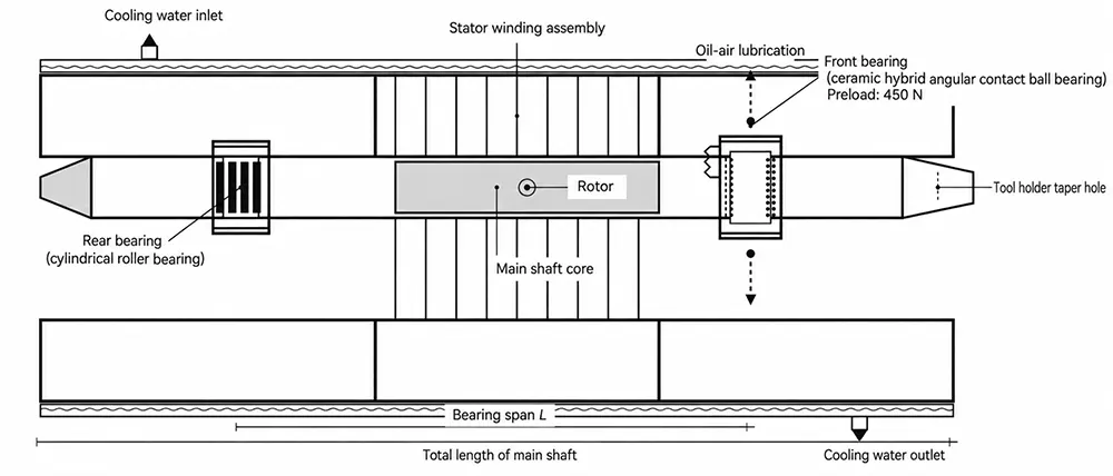
(1) The bearing configuration employs a combination of a front-end ceramic hybrid angular contact ball bearing and a rear-end cylindrical roller bearing.
The preload of the front bearing is set to 450 N, which keeps radial runout within 0.002 mm.
(2) The cooling system combines oil-air lubrication with circulating water cooling, which keeps the spindle temperature rise within 15 °C and limits thermal expansion to just 0.008 mm.
(3) Dynamic balancing accuracy reaches G2.5 grade, with residual unbalance less than 2 g·mm. The formula for calculating spindle stiffness is:

In the equation, Ks represents the spindle stiffness, F represents the radial load, δ represents the radial displacement, E represents the modulus of elasticity, I represents the moment of inertia of the cross-section, and L represents the span.
Test results show that the static stiffness at the front end of the spindle reaches 180 N/μm, meeting the requirements for precision machining of complex surfaces.
Intelligent Control System Integration Technology
The intelligent control system achieves adaptive optimization of the machining process through multi-sensor data fusion.
It integrates force sensors, vibration sensors, and temperature sensors to form a real-time monitoring network with a sampling frequency of 10 kHz.
The adaptive feed control algorithm dynamically adjusts the feed rate based on fluctuations in cutting force.
When the cutting force exceeds the set threshold of 5,500 N, the feed rate is automatically reduced by 15% to 25% to prevent tool chipping and workpiece deformation.
The system adopts current signal analysis for tool wear monitoring and triggers a tool replacement alert when the spindle current rises by more than 12%.
The control system optimizes the interpolation cycle to 1.5 ms and maintains contour error within ±0.004 mm.
Researchers adopt digital twin technology to build a virtual machining process model and apply genetic algorithms to optimize cutting parameter combinations.
This technical combination increases the efficiency of complex surface machining by 42%.
It also improves the consistency of workpiece surface quality by 38%.
Machining Process Testing and Performance Validation of Complex Parts
Test Plans for Machining Typical Complex Parts
To fully validate the performance of the optimized CNC lathe, we conduct machining tests on three typical types of complex parts.
(1) Thin-walled cylindrical part: Made of 7075 aluminum alloy, with an outer diameter of Φ120 mm, a wall thickness of 2 mm, a length of 180 mm, and a roundness tolerance of 0.01 mm.
(2) Shafts with non-circular cross-sections: Material is 45# steel, normalized and tempered;
The long axis of the elliptical cross-section is Φ85 mm, the short axis is Φ65 mm, length is 220 mm, and the contour tolerance is 0.015 mm.
(3) Complex curved rotary part: Made of TC4 titanium alloy, with a maximum diameter of Φ95 mm.
The curved surface consists of three sections with different radii of curvature (R15, R30, R45), and the surface roughness requirement is Ra 0.6 μm.
The tooling system is equipped with carbide indexable inserts with a front angle of 12° and a back angle of 8°.
The cutting parameters are set as follows: for thin-walled parts, a cutting speed of 180 m/min, a feed rate of 0.08 mm/r, and a depth of cut of 0.3 mm;
For steel parts, a cutting speed of 120 m/min, a feed rate of 0.12 mm/r, and a depth of cut of 0.5 mm;
For titanium alloys: cutting speed 60 m/min, feed rate 0.06 mm/r, cutting depth 0.2 mm, using a minimal-quantity lubrication cooling method.
Machining Accuracy Testing and Analysis
We test the dimensional accuracy of machined parts with a coordinate measuring machine and surface roughness meter, and summarize the measured data in Table 3.
The thin-walled cylindrical part had a roundness error of 0.008 mm and a cylindricity error of 0.011 mm, both of which met the design requirements.
The machine controls wall thickness uniformity deviation within ±0.015 mm with no obvious structural deformation detected.
For non-circular cross-section shaft components, the contour error was 0.012 mm;
The dimensional errors for the long and short axes were +0.006 mm and −0.004 mm, respectively; and the positional error was 0.009 mm.
For complex curved surface components, the dimensional errors at each measurement point fell within ±0.005 mm, and the transitions at the junctions of the three curved surfaces were smooth, with no noticeable steps.
Surface roughness tests showed that the Ra values were 0.65 μm for aluminum alloy parts, 0.75 μm for steel parts, and 0.58 μm for titanium alloy parts, all meeting the expected specifications.
This research analyzes the key factors affecting machining performance.
Spindle thermal deformation compensation enhanced the dimensional accuracy by 35%.
Adaptive feed control improved the surface quality with a contribution rate of 42%.
Bed rigidity optimization effectively restrains machining vibrations of thin-walled parts.
In summary, the machining accuracy of all three types of complex parts met the design requirements, validating the high-precision machining capabilities of the optimized CNC lathe.
| Part Type | Dimensional Accuracy (mm) | Geometric Error (mm) | Surface Roughness Ra (μm) | Machining Time (min) |
|---|---|---|---|---|
| Thin-Walled Cylindrical Part | ±0.006 | 0.008 (Roundness) | 0.65 | 28 |
| Non-Circular Cross-Section Shaft | ±0.006 | 0.012 (Profile Tolerance) | 0.75 | 35 |
| Complex Curved-Surface Part | ±0.005 | 0.009 (Position Tolerance) | 0.58 | 42 |
Table 3. Machining Accuracy Test Results for Typical Complex Parts
Comparison of Machine Tool Performance and Industrial Applications
Comparative tests between the optimized CNC lathe and traditional machine tools showed a 40% increase in machining efficiency, a 55% extension in tool life, and a 28% reduction in energy consumption.
We perform a 72-hour continuous machining test to validate the machine tool’s operational stability.
The optimized machine tool maintained stable dimensional accuracy throughout the test.
Its dimensional accuracy standard deviation was only 0.0018 mm. In contrast, traditional machine tools achieved a standard deviation of 0.0065 mm.
The optimized design realizes a 260% improvement in machining stability.
In an application at an aircraft engine manufacturing company, the machine successfully machined the splines on turbine blades, achieving a tooth profile accuracy of IT6 grade and increasing the mass production yield rate from 83% to 96%.
A precision mold factory adopts the optimized lathe to machine injection mold cavities and controls the corresponding surface contour errors within 0.006 mm.
Practical applications demonstrate that the optimized CNC lathe has significantly improved the machining quality and production efficiency of complex parts.
Conclusion
To address the machining requirements of complex parts, we systematically conducted research and validation of key technologies for the manufacture of CNC lathes.
Topology optimization and rib layout improvement increase the bed’s static stiffness by 31% and raise the damping ratio to 0.089, which effectively restrains machining vibration.
The electric spindle system employs ceramic bearings and oil-air lubrication technology to achieve stable high-speed operation at 24,000 r/min, with thermal expansion of only 0.008 mm.
The adaptive control system integrates multiple sensors for force, vibration, and temperature to enable real-time optimization of cutting parameters, resulting in a 42% increase in machining efficiency.
This study performs industrial application validation on the optimized CNC lathe.
The equipment delivers excellent performance in multiple high-precision fields.
Its application scenarios include aircraft engine components, precision molds, and medical devices.
The lathe achieves a machining accuracy of ±0.005 mm for complex parts with stable surface quality.
It marks a remarkable technological breakthrough in precision machining.