





Following the previous article...
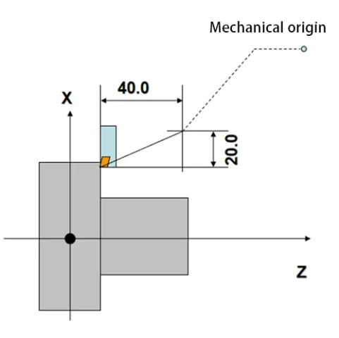
G28/G29 Automatic Home Position Return Commands
For machines configured with incremental measurement, the G28 automatic home position return command must be executed at startup.
Once executed, the machine’s home position return indicator light will illuminate to confirm completion.
Command Format: G91G28G0X0Y0Z0; (Essential Operational Skill)
During machining, it may be necessary to execute the G28 command to return to the origin.
At the same time, it may be required to return to a command point.
In this case, the G29 command can be used to accomplish this task.
Additionally, when returning to the origin, the machine can pass through an intermediate point to avoid obstacles.
G28 X(U)—Z(W)—; where X(U) and Z(W) are the coordinates of the intermediate point
G29 X(U)—Z(W)—; return to the command point
Example: G28U40.0W40.0;
G29U40.0W40.0
G32 Thread Cutting
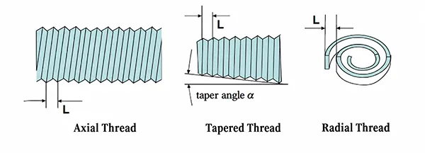
This command is used for cutting axial threads, helical threads, and radial threads.
Command Format:
1) Axial thread: G32 Z (W)—-F—-;
Helical thread: G32 X (U)—-Z (W)—-F—-; or F may be represented by E.
Radial threads: G32 X (U)—-F—-;
Notes:
For the minimum value of thread pitch L, F is 0.01 mm and E is 0.0001 mm
For a thread angle α ≤ 45°, pitch L corresponds to the length measured along the Z-axis.
Where the thread angle α > 45°, pitch L denotes the length along the X-axis.
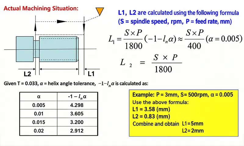
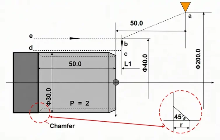
During thread cutting, account must be taken of pitch distortion from incomplete tool entry and exit, stemming from the servo-system time constant T ≈ 0.033 s; refer to dimensions L1 and L2 in the figure.
Example: Thread outer diameter φ30, pitch 2 mm, material S45C. Please write the program.
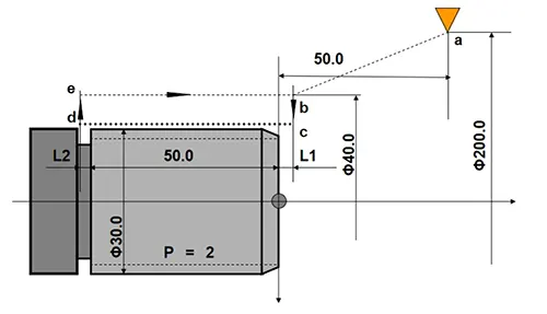
1) Determine the spindle speed (S) using the formula S = 5000/P = 5000/2 = 2500 rpm (MAX)
2) Determine the cutting speed: Set it to 100 m/min based on the assumed material S45C

3) Calculate the incomplete thread pitches L1 and L2

In practice, S is less than 1000 rpm, and L1 and L2 are greater than the calculated values.
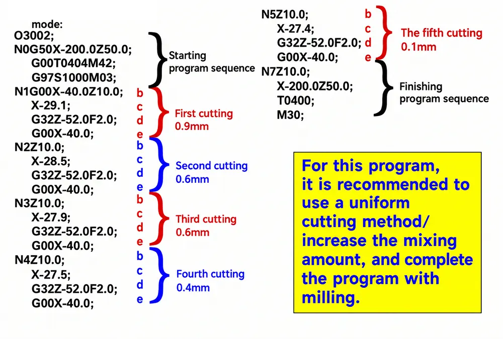
4) Determine the cutting depth and number of cuts:
First cut: 0.9 mm; First cut: 0.6 mm
First cut: 0.6 mm; First cut: 0.4 mm
First cut: 0.1 mm
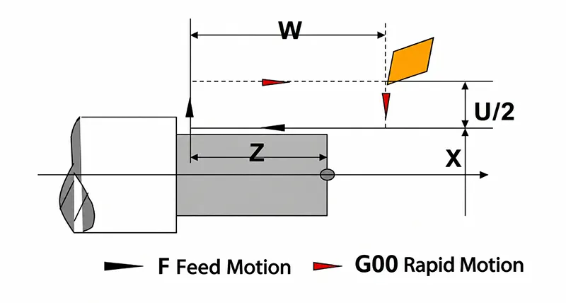
G90 Fixed-Diameter Cycle Cutting
1) Linear Fixed-Diameter Cycle Cutting: Command format: G90X (U)—-Z (W)—-F—-
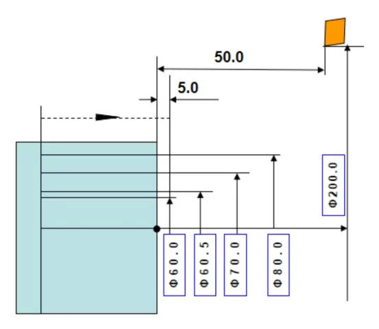
Example: Using the fixed-cycle method, machine a φ90 workpiece into a φ60 round bar.
1. Machine in four passes: φ80, φ70, φ60.5, and φ60.0.
2. Program using absolute coordinates.
3. Set the tool starting point at X=200.0, Z=50.
4. Programming:
O3333;
N1G50X-200.0Z50.0;
G00G96S150M42T0101;
M03;
X-100.0Z5.0;
N2 G90 X-80.0 Z-60.0 F0.35;
X-70.0;
X-60.5;
X 60.0 F0.15;
N3 G00 X-200.0 Z50.0;
T0100;
M01;
G92 Thread Cutting Cycle
1) Command Format: G92X (U)—-Z (W)—-F (E)—-;
The difference between this command and G32 is that it adds a retraction of approximately 45 degrees at the end of the thread;
The radius (r) at the retraction point is set by a parameter. Other details will not be discussed here; we will use the G32 example to program in G92.
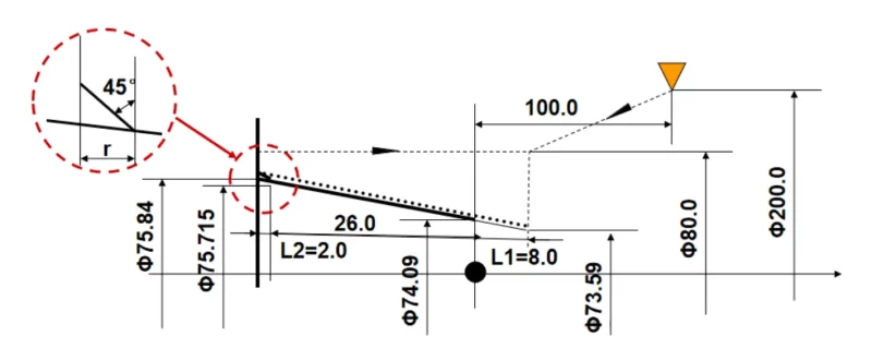
Example: Programming for turning a PT 2 ½ pipe thread on S45C material
1) Referring to the table, we find: pitch = 2.3091 mm, thread height = 1.479 mm, taper angle = 1/16.
2) Calculations
S1 = 4000/P = 4000/2.3091 = 1732 rpm
S2 = V × 1000/3.14 × D = 100 × 1000/3.14 × 75 ≈ 425 rpm (S = 425 rpm)
3) Calculations
L1 = S × P / 400 = 425 × 2.3091 / 400 = 2.45 mm
L2 = S × P / 1800 = 425 × 2.3091 / 1800 = 0.545 mm
Take: L1 = 8 mm; L2 = 2 mm (The value of 8 mm is chosen here based on the taper angle.)
G94 Face-Fixed Cycle Cutting
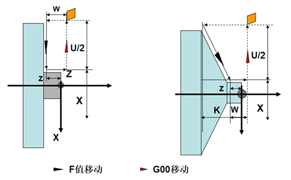
1) Face-Fixed Cycle Cutting: Command format: G90X(U)—-Z(W)—-F—-;
2) Inclined-Face Fixed Cycle Cutting: Command format: G90X(U)—-Z(W)—-I—-F—
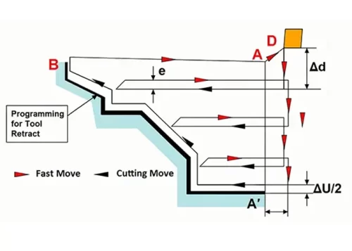
G71—Axial Cycle Cutting
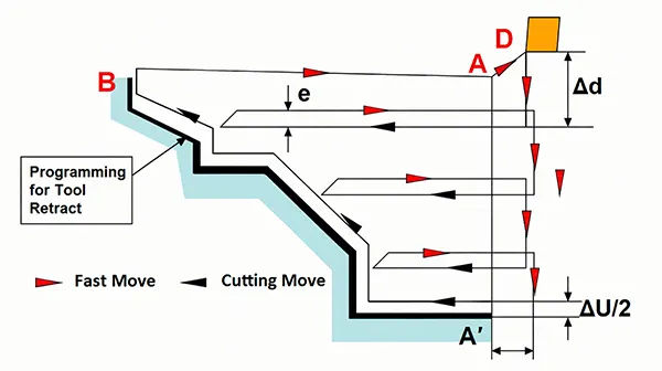
This command is used to perform cycle cutting for both roughing and finishing along an axial path.
Command Format:
G71P(NS)Q(Nf)U(ΔU)W(ΔW)D(Δd)F—-S—-T—-;
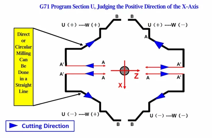
Where: P—Program number (NS) determining the start of the finishing path (A–A′–B).
Q—Program number (Nf) determining the end of the finishing path (A–A′–B).
U—Finishing allowance (ΔU) and direction in the X-axis. (Diameter command)
W—Finishing allowance (ΔW) and direction in the Z-axis.
D—Depth of cut per pass (Δd), with no positive or negative sign. (Radius command)
F, S, T—In the machining path from program P to Q, F, S, and T are invalid when executing G71. However, they are valid within a single G71 block.
Program:
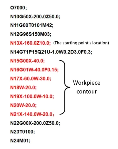
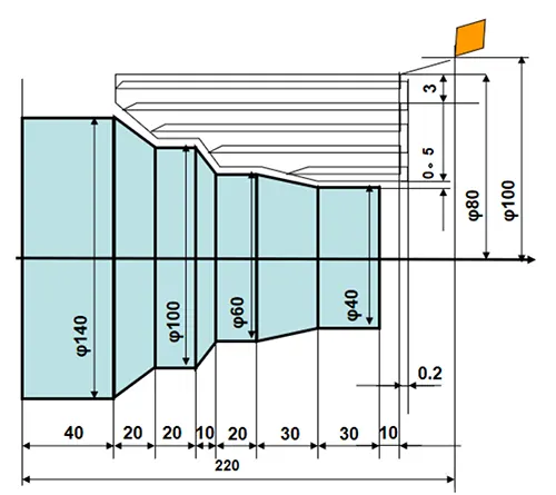
Machine the stepped shaft shown below using axial recirculation:
G72—Face Recirculating Cutting
This command is used for rough machining various curves on a face. The difference from G71 is that the machined surface is closer to the X-axis; otherwise, it is similar to G71.
G70—Finishing Cycle
Use this command for finishing operations following roughing with G71, G72, or G73.
Command format: G70 P(ns) Q(nf);
ns—The sequence number of the first block in the finishing program.
nf—The sequence number of the last block in the finishing program.
Notes:
1) The F, S, and T parameters specified in G71–G73 program blocks are invalid; however, they are valid for sequence numbers ns–nf during G70.
2) When the G70 cycle ends, the tool returns to the starting point and executes the next program instruction.
3) G70–G73 must be run in AUTO mode, and no subprograms may be called between Ns and Nf.
Tool Compensation Function: Since the tip of an actual cutting tool—whether large or small—always has a radius R, errors occur when machining inclined surfaces or arcs.
See the following two examples:
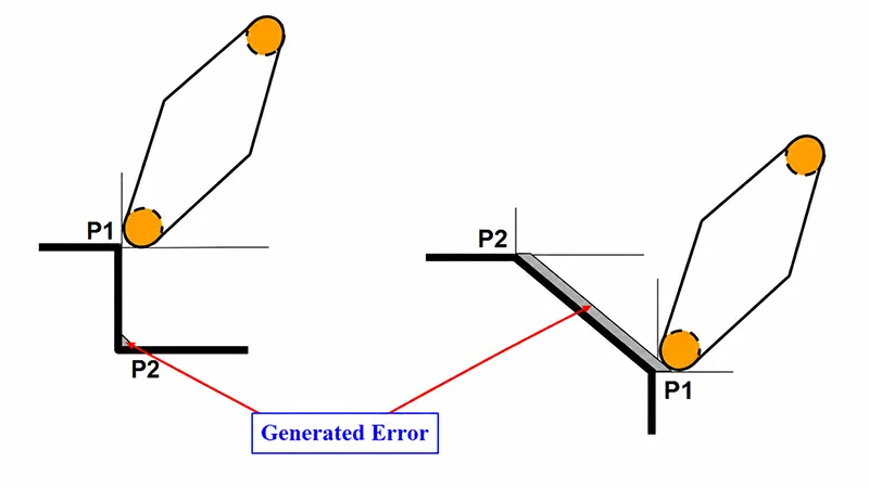
Calculations taking tool radius into account
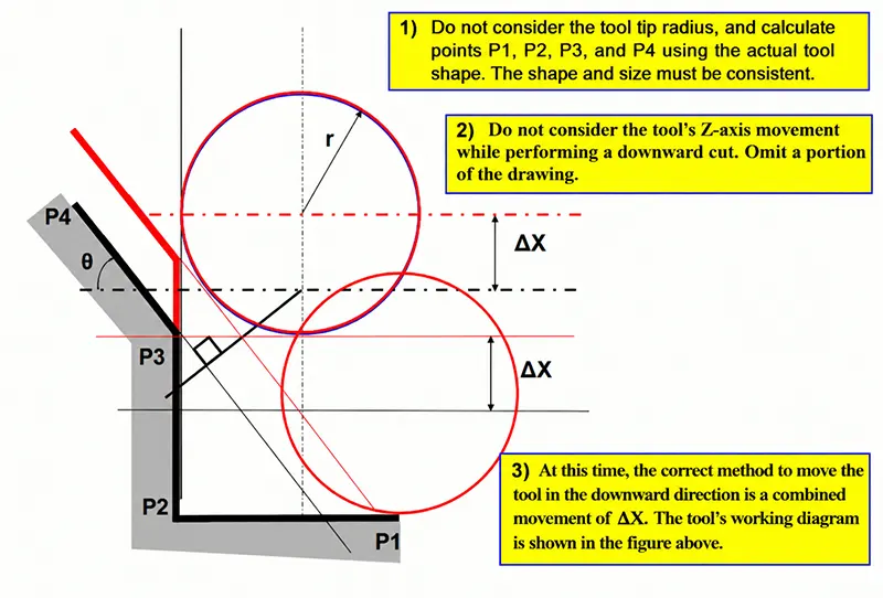
Calculations taking tool radius into account
4) Calculate the tool offset. (It is also possible to move simultaneously in the X and Z directions, though this makes the calculation more complex.)
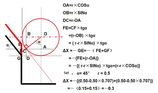
As can be seen from the example above, even a simple chamfer calculation is this difficult; machining arcs is even more challenging.
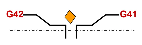
Tool Radius Compensation Functions (G40, G41, G42)
1) Left Tool Radius Compensation G41—Tool radius compensation when the tool is on the left side of the workpiece, as viewed in the direction of tool movement (forward).
2) Right Tool Radius Compensation G42—Tool radius compensation when the tool is on the right side of the workpiece, as viewed in the direction of tool movement (forward).
3) Cancel Tool Radius Compensation G40—This command is used to cancel the effects of commands G41 and G42.
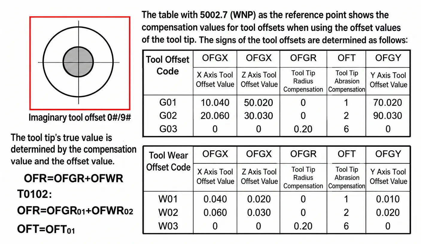
Setting the Apparent Tool Tip Direction: The apparent tool tip direction, as viewed from the center of the tool tip, is determined by the orientation of the tool during cutting and must be set in advance along with the tool offset value.
The apparent tool orientation is selected together with the corresponding T-code.
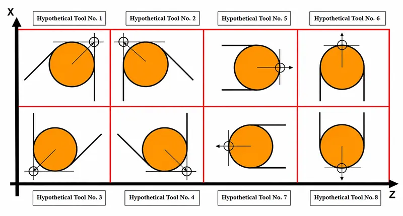
Note: The hypothetical cutting edge numbers 1–8 can only be used for G18 (Z-X plane); #0 and #9 can be used for G17 and G19 planes. The shapes of the #0 and #9 cutting edges are shown below.
The design of machining programs is a product of scientific progress and must be guided by a theoretical foundation.
At the same time, it is based on a wealth of machining experience, so it has a strong practical component.
Programming instructions and methods are merely tools;
To master them effectively, in addition to diligently studying the theoretical foundations, practical experience is even more essential.
“Practice is the sole criterion for testing truth.”
Conclusion
When it comes to programming and operating CNC lathes, safety standards are the foundation, commands are the core tools, and hands-on practice is the key to advancement.
From pre-operation checks to precision programming, and from basic commands to complex cycles—by thoroughly mastering the content in this article, beginners can get up to speed quickly, while experienced operators can take their skills to the next level with precision!
Bookmark this guide to avoid pitfalls in machining and programming and to have a solid foundation for daily operations.
Share it with your friends in the machining industry so you can all improve your skills together.
A quote to inspire us all: Your value lies not in never falling, but in standing up straighter after every fall.