





Injection-molded production performance depends heavily on the coordinated operation of injection molding machines and molds.
Mutual precision matching between components matters.
Rational mold structural design is essential. Appropriate process parameters should be set, and suitable materials need to be selected.
Together, these factors decide mold service life, dimensional accuracy of produced parts, and overall production stability.
This article analyzes the interactive influences between injection molding equipment and molds.
It further discusses the key design points of molds, which cover parting-line structure, mold base rigidity, positioning performance and maintainability.
It further investigates how molding processes, high-speed thin-wall injection requirements and mold material properties impact mold failure risk and service life.
The findings offer practical technical references for mold development and on-site injection molding production.
Precision Matching Between Injection Molding Machines and Molds
Injection molding machines and injection molds together form the basic system for injection molding.
The service life of the mold and the injection molding machine influence each other; the mold affects the injection molding machine in the following ways.
1. Fora large, single-cavity plastic part, the side gate is often offset from the center of the mold.
If the gate bushing deviates from the mold center by more than 30 mm, it will cause uneven wear on the injection molding machine’s guide pillars, affecting the machine’s precision.
The mold base size should be increased, and counterweights should be designed in the non-cavity areas to ensure that the machine’s clamping force is applied evenly to the mold.
2. Onlarge injection molding machines, using a mold that is too small can also affect the machine’s precision.
3. Excessivedeviation in the parallelism of the mold plates will affect the machine’s precision.
The precision of the injection molding machine also significantly affects the precision of the mold.
The guiding accuracy of the machine’s four guide pillars, as well as the parallelism between the moving mold mounting plate and the fixed mold mounting plate, all influence the precision of the injection mold.
Therefore, precision molds should be molded using injection molding machines with high precision.
The Impact of Mold Design
Mold design has a significant impact on the stress conditions within a mold.
The more complex the product design, the more complex the corresponding mold design becomes, leading to an increase in vulnerable areas.
The parts of an injection mold most prone to failure include slider core-pulling mechanisms, small-diameter or high-angle ejector pins, fine inserts, fine ejector pins and ejector rods, and guide pins.
Influence of Parting Line Structural Design on Mold Life
The rationality of the parting line design has a major impact on mold life.
The parting line of a plastic part may feature dramatic undulations and complex geometry.
Under such conditions, the structure commonly contains multiple characteristic regions.
These include areas where the core penetrates the cavity, regions where the core collides with the cavity, and positions where the core bears against the cavity wall.
1. Risks and Optimization of Piercing Structures
Frequent core-cavity penetration areas are highly susceptible to flash defects.
Penetration designs, also referred to as piercing designs, impose severe working conditions on the sealing surfaces between core and cavity.
These sealing surfaces are prone to wear, indentation, collapse and surface scuffing.
Such surface damages will further induce flash generation on molded plastic parts.
Among all molded part parting lines, penetration is the most dangerous type and has the shortest service life; therefore, it is generally avoided whenever possible.
A separate insert structure is recommended for the piercing part of the moving die in piercing design.
The material and hardness of this movable insert should be slightly lower than those of the fixed die insert.
This structural and material matching method effectively protects the cavity of the fixed die.
A piercing structure can be avoided by designing a lateral parting mechanism using sliders, though this will increase mold cost.
When a piercing structure is absolutely necessary, use the largest possible piercing angle while ensuring the dimensional tolerances of the plastic part are maintained.
2. Advantages of Pillow-Type (Bump-Through) Structures
The term “bump-through”, also named “butt-break”, describes a specific mold structural condition.
In this case, the sealing surface for molten plastic inside the part is perpendicular or nearly perpendicular to the mold opening direction.
This sealing surface corresponds to the contact interface between moving and fixed mold inserts.
Pillow-type structures involve far lower risks compared with piercing structures.
Meanwhile, they achieve a remarkably longer service life.
Accordingly, designers should adopt pillow-type structures to replace piercing structures whenever feasible.
Influence of Mold Integral Structure and Positioning Design on Rigidity and Life
The mold design significantly affects mold life.
There is a substantial difference in strength and rigidity between monoblock molds and assembled molds.
The concave fillet radius in monoblock molds is prone to causing stress concentration, which can lead to cracking.
Whether a mold requires separable inserts and whether a fully assembled insert structure should be adopted must be determined through systematic analysis.
Molds equipped with guide devices ensure the positional accuracy of all relevant components within the mold, enhance the mold’s resistance to bending and off-center loading, and prevent uneven wear.
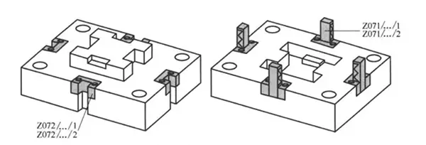
In molds with small inserts that pass through the mold body, precision positioning features—such as zero-degree positioning blocks—can help protect the small inserts.
Precision positioning on the mold base is effective only when the guide angle is less than or equal to the angle at which the small insert passes through.
Precision positioning features on the mold base must be specified at the time of ordering; those added later are unlikely to function effectively due to machining accuracy limitations.
See Figure 1-1 for the HASCO zero-degree positioning block.
The mold base is the primary component of a mold and serves as the support for other parts; therefore, it must not only meet strength requirements but also possess good rigidity.
Mold plates should not be too thin; they should have an appropriate thickness while still fitting within the injection molding machine’s mold cavity space.
Domestically produced molds commonly suffer from insufficient thickness of mold plates.
This problem mainly stems from inadequate awareness of the significance of mold base rigidity.
To prevent deformation and warping of the mold base in commercial molds, the thickness of the mold plates and the width of the mold plates at the edges of the core should be increased.
Maintainability Optimization Design for Mold Structural Service Life
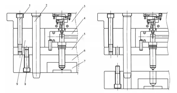
During mold design, the scope of disassembly required to service a specific component should be minimized, particularly when replacing wear-prone parts.
Special considerations apply to the disassembly of hot-runner molds.
When the hot-runner system works normally, only the mold inserts require removal.
Disassembly of the hot-runner system is unnecessary under such conditions (see Figure 1-2).
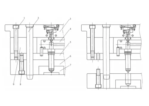
Design four locating pins 2 for the fixed platen, with a diameter of Φ30 or greater and a fit of H7/g6 relative to the platen.
Their length should extend beyond the tip of the hot nozzle to protect it from damage during assembly.
When assembling or disassembling the mold for maintenance, only the fixed platen mounting bolts 8 need to be removed;
The hot runner system, which is secured to the three platens on the top surface, does not need to be disassembled, thereby facilitating mold maintenance.
This design introduces an additional hot nozzle mounting plate 5, which raises the overall mold cost.
Nevertheless, the structure facilitates convenient maintenance and brings considerable cost savings.
These savings greatly offset the expense of the extra plate. Therefore, this design is worthy of popularization.
The Impact of Mold Component Design on Machinability
A well-designed mold component structure ensures that forces are distributed evenly during mold operation, minimizes the risk of off-center loading, and reduces stress concentration.
Fillet radii should be incorporated in non-sealing areas, and the size of the fillet radius (R) must be determined based on the machining process and cutting tools.
Fillet radii are classified as outer (convex) fillet radii and inner (concave) fillet radii.
The size of the fillet radius in the working area not only affects the molding process and the quality of the molded parts but also influences the failure modes and service life of the mold.
The Impact of Injection Molding Processes on Mold Life
Plastic materials have a significant impact on mold life. In particular, molding plastics containing additives such as glass fiber causes severe wear on the mold.
When molding high-temperature plastics, the mold heats up as it absorbs heat.
As the temperature rises, the mold’s strength decreases, making it prone to plastic deformation.
Meanwhile, the mold presents a prominent temperature difference between part-contact surfaces and non-contact surfaces.
This temperature disparity induces thermal stress inside the mold.
Thermal expansion narrows the clearance of moving components.
Typical examples include guide pins, guide bushings, sliders and angled ejectors.
This condition may cause unsmooth movement and further accelerate component wear.
Therefore, precision molds require the use of ball-bearing guide bushings or guide components containing graphite lubrication, along with cooling around these guide components.
High-Speed Molding
The advantage of thin-wall injection molding is that the reduced wall thickness of the molded part requires less material to be cooled, which can cut the molding cycle time in half.
Injection speed is one of the key factors for successful thin-wall injection molding.
Rapid filling and high pressure allow the molten thermoplastic material to be injected into the mold cavity at high speed, thereby preventing gate cold solidification.
Currently, in the injection molding of thin-walled PE tableware, the shortest molding cycle has been reduced to less than 3 seconds, and this high efficiency has yielded significant returns.
Machine Parameter Requirements for Thin-Wall Injection Molding
To withstand the high pressure of new injection molding machines, the minimum clamping force must be 5–7 t/in (projected area).
Additionally, as wall thickness decreases and injection pressure increases, a large platen helps reduce bending. For thin-wall products, the ratio of tie bars to platen thickness on the injection molding machine is 2:1 or lower.
When producing thin-wall products, closed-loop control of injection speed, pressure, and other process parameters helps manage filling and holding pressure under high pressure and high speed.
Impact of High Injection Speed on Mold Load and Material Selection
During the injection molding process, the injection molding machine undergoes elastic deformation due to the reaction force from the mold.
The injection pressure applied by the machine to the mold increases gradually over time, and the injection speed influences this force application process.
The higher the injection speed, the greater the impact force the mold experiences per unit of time;
The action takes place within a short time span.
Impact energy cannot be fully transferred or dissipated. Instead, such energy tends to concentrate in local regions.
Consequently, local stresses may surpass the yield strength or fracture strength of the mold material.
Therefore, the higher the injection speed, the more likely the mold is to fracture or fail due to plastic deformation.
Consequently, high-speed injection requires careful consideration of the mold material.
P20 steel is widely used in the injection molding of traditional products;
However, because thin-wall injection molding involves higher pressures, the mold must be exceptionally robust.
H13 and other heat-treated steels are the preferred materials for thin-wall injection molds.
Structural Optimization of Hot Runner Manifold Plates
In high-speed molding, hot runner systems are widely used.
High speed and high pressure place greater demands on the manifold plates of hot runner systems;
In addition to selecting high-quality steel, the structure of the manifold plates also requires improvement.
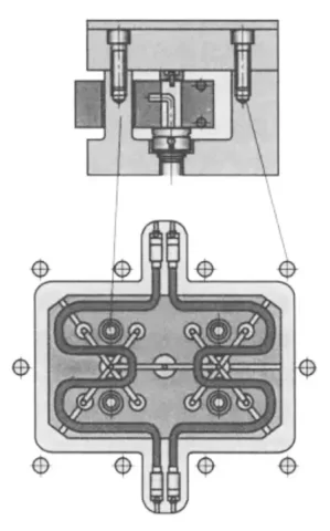
Figures 1–3 show a high-strength manifold designed by EWIKON.
A void is incorporated at the center of the manifold, and support pillars are integrated into the mold plate, effectively increasing the plate’s rigidity and strength.
Additionally, the number of mounting bolts at the edges of the mold plate has been increased to enhance connection rigidity.
The Impact of Mold Material Properties
The properties of mold materials have a significant impact on mold service life.
These properties include: strength, impact toughness, wear resistance, corrosion resistance, hardness, thermal stability, and heat fatigue resistance.
In summary, the following aspects should be considered when selecting mold materials:
First, the heat treatment process for the mold material should be simple and straightforward, with minimal thermal deformation;
Second, the material should have good wear resistance, as well as high hardness, strength, and toughness;
Third, the material must possess good machinability, electrical discharge machining (EDM) performance, and polishability.
FCVA vacuum-deposited diamond coating technology is an emerging advanced process in recent years.
It can form a protective layer on component surfaces.
This coating achieves extremely strong bonding with the substrate.
Meanwhile, it features superior smoothness, uniformity and compactness.
This technology is particularly suitable for protective surface treatment of molds and is also a highly effective method for improving mold quality.
Conclusion
The reliable operation of injection -molding systems requires good precision matching between the injection molding machine and the mold;
Offset gate positions, undersized mold dimensions, and unsatisfactory mold plate parallelism will compromise the overall precision of molding equipment.
In turn, low-precision equipment fails to meet the assembly and operation requirements of high-precision molds.
Mold design is decisive for service life: piercing parting-line structures should be avoided where feasible, and pillow-type butt-break structures are preferred.
Sufficient mold -base rigidity, reliable precision positioning mechanisms and maintainable modular layouts effectively reduce stress concentration and component wear.
Molding conditions such as abrasive-filled plastics and large mold temperature differences accelerate mold deterioration.
High-speed thin-wall injection molding imposes rigorous working conditions.
Sufficient clamping force and robust hot-runner manifold structures are indispensable.
In addition, high-strength heat-treated mold steels represented by H13 are required.
These configurations effectively resist concentrated impact stress during production.
Reasonable material selection covering strength, toughness, wear resistance and thermal fatigue performance, paired with advanced surface -coating treatments, can further extend mold working life.
Balancing equipment -mold matching, structural design, process constraints and material performance helps minimize premature mold failure and stabilizes mass-production quality.