





Titanium alloys are high-performance metallic materials. Due to their low density, high specific strength, excellent corrosion resistance, and high-temperature resistance, they are widely used in fields such as aerospace, marine engineering, and medical devices.
Thin-walled curved titanium alloy housings possess compact structure and lightweight characteristics.
Owing to these superior properties, they are widely applied as critical components in aero-engine core structures and precision instruments.
However, the inherent properties of titanium alloys—low thermal conductivity, low modulus of elasticity, and high chemical reactivity—result in poor machinability.
Coupled with the insufficient rigidity of thin-walled curved structures, various quality issues can easily arise during the machining and forming process, severely affecting product precision and production yield.
Therefore, research on optimizing deformation control during the machining and forming of thin-walled curved titanium alloy housings holds significant engineering and practical value.
Machining Challenges
The challenges in machining thin-walled, curved titanium alloy housings stem primarily from both the material properties and structural characteristics.
The thermal conductivity of titanium alloys is only 1/7 that of steel and 1/16 that of aluminum.
Heat generated during machining cannot be rapidly dissipated and tends to accumulate in the cutting zone, causing temperatures there to exceed 1,000 °C.
This accelerates tool wear and chipping, compromises the surface integrity of the part, induces work hardening, and reduces the part’s fatigue strength.
At the same time, titanium alloys have a low modulus of elasticity, and thin-walled curved structures lack structural rigidity.
Workpieces will bear external loads including clamping forces and cutting forces during machining.
Under these loads, thin-walled curved titanium alloy housings tend to produce elastic and plastic deformation.
This deformation causes contour accuracy deviations of curved surfaces and uneven wall thickness.
Furthermore, the complexity of the curved structures makes it even more difficult to control deformation.
Additionally, defects such as burrs and uneven surface roughness may arise during the machining process, thereby affecting product quality.
Current Research Status and Existing Limitations
Current global research on titanium alloy machining mainly concentrates on cutting parameter optimization and tool selection for conventional titanium alloy components.
In contrast, specialized investigations targeting thin-walled curved titanium alloy housings remain insufficient.
Regarding the optimization of titanium alloy machining processes, current research largely focuses on improving tool materials and geometries, as well as adjusting cutting parameters.
YG-type cemented carbide tools, which have good red hardness but poor affinity with titanium alloys, are used to reduce cutting temperatures and minimize tool wear by adjusting parameters such as cutting speed and feed rate.
Regarding deformation control of thin-walled parts, researchers believe that improving fixture design and clamping methods are the primary means of controlling machining deformation.
Existing studies have adopted elastic mechanics analysis and finite element simulation methods to explore thin-walled part deformation.
These investigations focus on the influences of different clamping layouts and clamping forces on workpiece deformation.
Based on the research findings, dedicated fixtures have been developed to suppress the deformation of thin-walled workpieces.
Others have employed methods such as axial clamping and the addition of process ribs to reduce uneven force distribution during clamping, thereby ensuring dimensional accuracy and geometric tolerances of the parts.
Although research on titanium alloy machining has achieved certain results, there are still significant shortcomings in the study of thin-walled, curved titanium alloy housings.
Specifically, research into the deformation mechanisms caused by the coupled effects of curved structures and material properties has not been sufficiently in-depth;
The design of specialized fixtures and the optimization of clamping parameters lack specificity;
Research on the coordinated optimization of cutting processes and deformation control is insufficient;
And a systematic deformation control plan has not yet been established.
Research Objectives and Optimization Approach
This paper targets two key problems occurring in the CNC milling of thin-walled curved titanium alloy housings, namely machining deformation and cutting chatter.
The research is carried out from two dimensions, including the machining process mechanism and structural dynamic characteristics of the workpiece.
It conducts a mechanistic analysis solely of the deformation inheritance effects resulting from the preceding hot forming process, without performing hot forming simulations or process experiments.
Finite element simulation was performed in this study to support quantitative analysis of the milling process.
Sensitivity analysis of clamping parameters and exploration of cutting force variation patterns were systematically carried out.
The critical positions prone to deformation and stress concentration under milling conditions were accurately identified.
A central-pin auxiliary support fixture was designed and parametrically optimized to suppress cutting chatter at the structural level;
Factory-proven hot-formed and stress-relieved annealed blanks were used as test specimens.
Actual milling operations and precision inspections were implemented to validate the optimized milling scheme.
This approach improves the machining accuracy and batch pass rate of the milling process, and offers technical guidance for the CNC milling of similar parts.
Machining and Forming of Titanium Alloy Covers
Part Structure and Material Properties
Titanium alloys possess unique material properties, including high strength, excellent corrosion resistance, and high thermal stability.
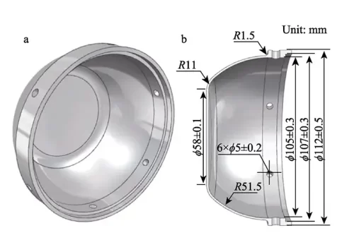
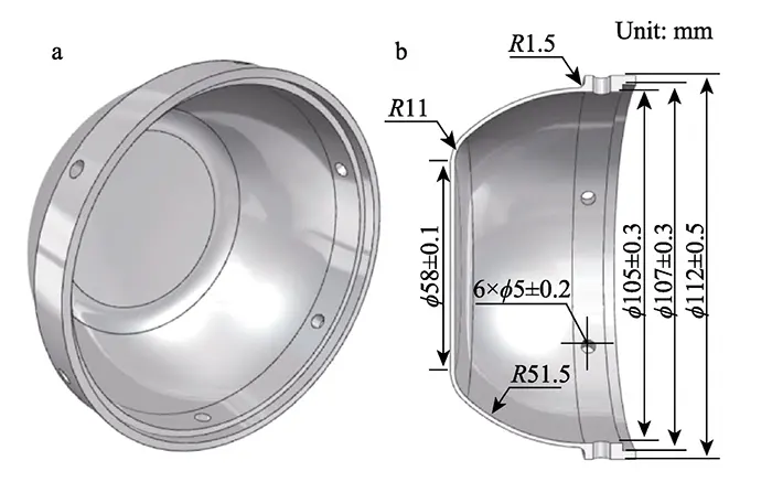
The titanium alloy housing studied in this paper is used for protection in aircraft engines, serving to provide sealing, thermal insulation, and structural support.
A schematic diagram of its structure is shown in Figure 1. TC4 titanium alloy is used as the material;
This alloy features an α+β dual-phase structure and has good overall mechanical properties, capable of meeting stringent in-service requirements.
The housing is an irregular thin-walled shell structure with a complex contour surface and uneven wall thickness distribution.
There are significant variations in overall stiffness distribution, with the central bottom region exhibiting the lowest stiffness.
Composite Machining Process
The primary machining and forming method for this housing is a composite process consisting of “rough forming by stamping + finishing by CNC milling.”
Hot forming effectively improves the plasticity of titanium alloys and reduces machining difficulty; first, a rough blank with an approximate contour is obtained through hot pressing using a die;
Subsequent CNC milling for finishing involves the cutting tool moving along the surface trajectory of the housing according to a preset program to remove excess material, ensuring dimensional accuracy and surface quality.
This composite machining method balances forming efficiency with machining accuracy, meets the machining requirements of the housing’s complex structure, and enables stable medium-volume production.
The machining process is shown in Figure 2.
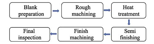
Based on the titanium alloy housing machining process shown in Figure 2, the specific processes for the main operations are as follows:
1. Rough Machining
Remove more than 90% of the excess material with maximum efficiency, quickly machining the raw material into a shape close to the final product’s contour.
A combination of low spindle speed, high feed rate, and multi-pass cutting, coupled with a high-rigidity roughing tool and strong axial clamping, maximizes cutting efficiency.
While ensuring that machining reference surfaces remain undamaged, a uniform machining allowance of 0.5–1.5 mm is left to provide sufficient space for subsequent operations.
2. Stress-relief Annealing
Eliminate cutting stresses generated during rough machining, stabilize part dimensions, and prevent deformation in subsequent machining operations by using a vacuum annealing process or a stress-relief annealing process (held at a temperature range of 600–650 °C).
3. Semi-finishing
Correct heat treatment distortion, further reduce the machining allowance, and provide a precise reference for finishing.
Appropriately increase the cutting speed while reducing the feed rate and cutting depth;
Begin using form turning tools to perform preliminary shaping of complex contours, leaving a uniform machining allowance of 0.1–0.3 mm for final finishing.
4. Finishing
Ensure stable clamping using high-precision fixtures such as hydraulically expandable mandrels;
Use high-precision form turning tools or polycrystalline diamond (PCD) tools, employing high spindle speeds, small feed rates, and fine cutting depths in conjunction with a high-pressure, high-flow cooling system.
Although composite machining can meet basic shaping requirements, the machining characteristics of TC4 titanium alloy pose significant challenges to the shaping quality of the housing.
Titanium alloys are highly chemically active and are prone to adhesive wear with the tool material during cutting, which reduces tool life and thereby affects the dimensional stability of the machined parts;
Heat generated during cutting concentrates in the cutting zone, easily
causing thermal deformation of the workpiece and compromising the accuracy of the curved surface profile.
This study focuses on the CNC milling finishing process and does not conduct simulation or experimental research on the thermal stamping roughing process;
Both simulations and milling tests directly use blanks that have undergone thermal forming and stress-relief annealing, with residual stresses and wall thickness deviations from previous processes serving as initial input conditions.
Mechanism of Deformation Inheritance in Hot Forming Processes
The mechanism of deformation inheritance discussed in this section is based on a qualitative, inductive analysis of common engineering phenomena observed in the hot forming of titanium alloys; no simulation of the hot forming process is conducted.
In the milling simulation, the residual stresses and wall thickness deviations of the blank—resulting from hot forming followed by stress-relief annealing—are used as initial input conditions, thereby indirectly reflecting the inherited effects from the preceding process.
Hot stamping rough forming is the first forming process in the manufacturing of thin-walled titanium alloy housings.
The initial residual stresses, wall thickness deviations, and contour distortions generated during this process exert a significant inherited influence on subsequent CNC milling finishing through inter-process transfer effects.
These factors are a major source of quality fluctuations in the finishing process, manifesting in three specific aspects:
1. Residual Stress Inheritance
During the hot forming process, the blank undergoes plastic deformation at high temperatures, and residual stresses arise during cooling due to temperature gradients and non-uniform phase transformations.
These residual stresses can only be partially eliminated during subsequent stress-relief annealing;
The remaining residual stresses redistribute as material is removed during milling, causing secondary deformation of the workpiece.
This is a major internal factor contributing to contour out-of-tolerance in the finishing process.
2. Inherited Geometric Deviations
Uneven initial wall thickness and surface contour deviations in the hot-formed blank lead to an uneven distribution of cutting depth during finishing.
This, in turn, causes fluctuations in cutting forces, increasing the risk of machining deformation and chatter.
At the same time, initial geometric deviations result in inconsistent contact conditions during clamping, generating additional clamping deformation.
3. Inherited Microstructural Variations
The temperature distribution during hot forming induces microstructural inhomogeneity in the blank and leads to localized mechanical property differences.
These variations ultimately affect the stress distribution and deformation behavior during machining.
Therefore, quality control of the hot forming process is a prerequisite for ensuring final machining accuracy;
Research must address the optimization of the hot forming process alongside the control of deformation and chatter during finishing as a systematic issue.
In engineering practice, initial residual stresses and contour deviations in blanks can be reduced by optimizing die surface compensation, heating parameters, and stress-relief annealing procedures.
These effective treatments create a reliable blank condition for subsequent milling processes.
Analysis of Clamping and Pre-stressing for Titanium Alloy Covers
Due to the inherently lightweight and thin-walled nature of titanium alloy covers, it is particularly important to conduct a proper clamping and stress analysis prior to machining.
Appropriate pre-stressing is not only a prerequisite for stable machining of the cover but also a means of preventing structural deformation and failure.
In this chapter’s simulation, the residual stresses in the blank following hot forming and stress-relief annealing are used as the initial stress field.
The clamping stress analysis is conducted while accounting for the stress inheritance effects from preceding processes.
Key Parameters for Finite Element Modeling
A finite element model was developed using general-purpose finite element software to analyze the clamping forces during the milling of a titanium alloy housing.
TC4 titanium alloy was selected as the material, and a bilinear, follow-up-strengthened elastoplastic constitutive model was adopted (TC4 is an α+β dual-phase titanium alloy;
In this study, simulations were conducted using average mechanical properties obtained from macroscopic material tests to analyze the workpiece’s macroscopic stresses and deformations).
The simulations in this section only model the pre-tensioning clamping process in which the workpiece is subjected to clamping forces;
This scenario does not involve heat generated by cutting (This model does not include coupled thermal-mechanical calculations for cutting;
In actual machining, high-pressure, high-flow cooling is used to maintain the workpiece temperature near 80 °C, thereby suppressing overall temperature rise;
Thermal deformation is not considered as a source of interference in the test results).
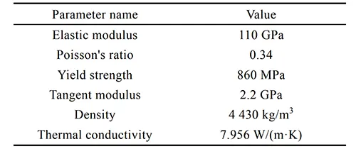
Since the workpiece is at room temperature, room-temperature mechanical parameters are used; the core mechanical parameters at room temperature are shown in Table 1.
Boundary Conditions and Contact Definition
Boundary constraints were set so that the pusher rod contacts the concave bottom of the housing, restricting the pusher rod’s translational degrees of freedom in the x, y, and z directions as well as its rotational degrees of freedom to simulate a rigid support;
The side of the housing’s inner edge assembly hole contacts the expansion fixture, configured as a face-to-face contact pair with a friction coefficient of 0.15.
The model employs an elastoplastic constitutive model.
Since the contact stresses during machining of this type of thin-walled structure fall outside the range of the material’s elastic deformation stresses, the effect of elastic deformation can be neglected here.
Mesh Generation and Model Validation
Mesh generation employs SOLID186 high-order 20-node hexahedral solid elements.
Given the thin-walled curved surface structure of the housing, the sweeping method is used to generate a structured mesh to ensure computational accuracy.
The global average element size is set to 2 mm, with local mesh refinement applied to areas with high stress gradients—such as the low-stiffness region at the center of the bottom and the clamping contact zones—where the element size in the refined areas is 0.8 mm.
Verification of mesh independence showed that the deviation between the results obtained with this mesh size and those from a further refined mesh was less than 2%, striking a balance between computational accuracy and efficiency.
The final model comprised approximately 12,000 elements and 25,000 nodes, with an average mesh Jacobian determinant greater than 0.85, indicating that the mesh quality met the requirements for finite element analysis.
Loading Method and Strength Evaluation
A progressive loading method was adopted to avoid numerical oscillations.
Five equal load steps were set, with 20% of the total pressure applied at each step.
Within each load step, five incremental sub-steps were defined to gradually increase the load to the target pressure;
The loading area was the inner surface of the assembly holes on the inner edge of the housing, where a uniformly distributed pressure ranging from 10 to 40 MPa was applied.
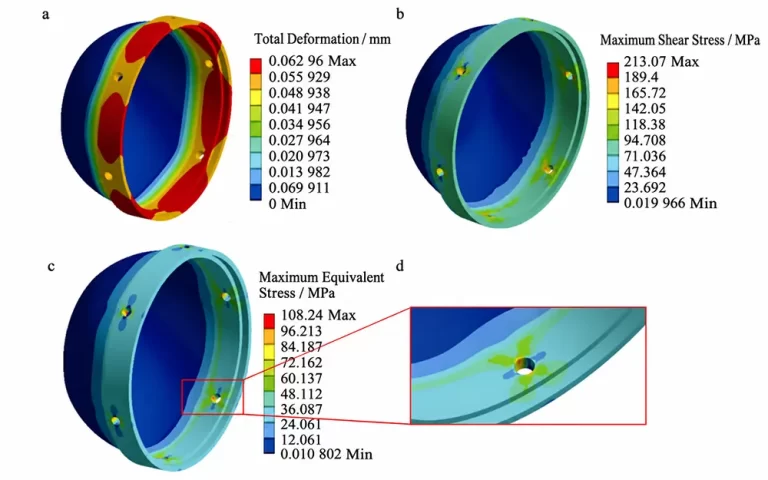
Strength checks were performed according to both the third and fourth strength theories, and the displacement, maximum shear stress, and maximum equivalent stress contour plots for the housing are shown in Figure 3.

Mechanical Response Patterns Under Different Loads
As shown in Figure 3, the primary load-bearing area for this clamping method is located at the assembly holes on the inner side of the housing’s inner edge.
The deformation, maximum shear stress, and maximum equivalent stress contour plots are consistent across different uniform locations.
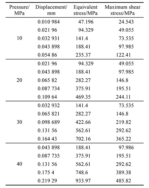
The mechanical response results in the 10–40 MPa range are summarized in Table 2.
Mechanical Response Under Different Clamping Loads
As shown by the mechanical results under different loads in Table 2, as the applied pressure increased from 10 MPa to 40 MPa, the equivalent stress and maximum shear stress of the cover both exhibited a significant positive correlation, consistent with the laws of stress in materials science.
Based on a clamping load of 30 MPa, the displacement range of this structure was 0.010 984–0.164 43 mm, the equivalent stress (Fourth Strength Theory) ranged from 47.196 to 702.16 MPa, and the maximum shear stress (Third Strength Theory) ranged from 24.543 to 365.22 MPa. with both showing synchronous trends and no signs of stress imbalance.
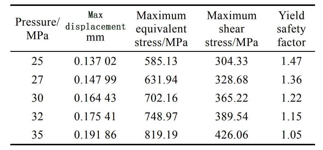
To further optimize the design, simulation points were densified in the 25–35 MPa range, and four additional load conditions (25, 27, 32, and 35 MPa) were added to conduct a single-factor parameter sensitivity analysis.
The results are shown in Table 3.
Clamping Pressure Sensitivity Analysis
Based on the sensitivity analysis results, it can be concluded that the clamping pressure exhibits a strictly linear relationship with displacement and stress.
For every 1 MPa increase in pressure, the maximum displacement increases by approximately 0.0055 mm, and the maximum equivalent stress rises by approximately 23.4 MPa. Given this monotonic relationship, there is no need for global optimization via orthogonal experiments;
The optimal values are determined jointly by the strength and deformation constraints.
Determination of the Clamping Load
Under a load of 30 MPa, the structural yield safety factor is 1.22, which falls within the generally accepted engineering range of 1.1 to 1.3 for clamping thin-walled aerospace components.
At the same time, the clamping stiffness is sufficient to resist workpiece slippage caused by cutting forces;
Below 25 MPa, the clamping stiffness is insufficient, making the workpiece prone to micro-movement; above 35 MPa, the load approaches the material’s yield limit, posing a risk of plastic deformation.
Considering clamping reliability, deformation control requirements, and the strength safety margin, 30 MPa is determined to be the optimal clamping load parameter.
Analysis of Cutting Forces During the Machining of a Titanium Alloy Housing
During the actual machining of thin-walled, curved titanium alloy housings, the inner edge is secured and clamped in place.
The turning tool then moves from the outside toward the inside along the tool path, thereby completing the precise turning of the housing’s bottom surface.
The simulation in this chapter accounts for the initial residual stresses and wall thickness deviations inherited from the hot forming process to more closely approximate actual machining conditions.
Justification of the Static Equivalent Cutting Load
This paper adopts a static uniformly distributed pressure of 500 MPa as the equivalent turning load.
The rationale and scope of application for this method are explained as follows:
1. Alignment with Research Objectives
The core objective of this chapter is to compare differences in structural static stiffness at various cutting points and to identify areas of stress concentration and structural weakness, rather than to analyze the transient dynamic response of the cutting process.
2. Source of the Equivalent Load
The 500 MPa contact stress was calculated based on actual finishing parameters: a cutting speed of 80 m/min, a feed rate of 0.1 mm/r, and a depth of cut of 0.2 mm.
Using an empirical formula for titanium alloy turning forces, the steady-state principal cutting force was calculated to be approximately 120 N.
Combining this with the tool tip radius and contact area, the equivalent stress in the tool-workpiece contact zone was converted to approximately 500 MPa, which aligns with actual engineering cutting conditions.
The “relative magnitudes of stresses at different points and trends in stress concentration distribution” obtained from static load simulation are consistent with the patterns observed under dynamic conditions, enabling accurate identification of structurally weak areas.
For the process optimization of thin-walled parts, the core objective is to locate weak points and specifically enhance stiffness;
The static equivalent method possesses sufficient engineering validity and is a commonly used engineering approach for analyzing cutting deformation in thin-walled parts.
The turning setup is shown in Figure 4.
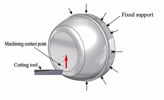
Using the center of the bottom of the titanium alloy housing as the origin, set evenly spaced turning contact points with a step size of 7 mm, apply an equivalent static cutting load of 500 MPa to the turning contact points, and determine their stress state.
Stress Distribution Patterns in Workpieces at Different Milling Cutting Points
Based on the turning setup for the titanium alloy housing shown in Figure 4, the center of the bottom of the titanium alloy housing was defined as the origin, and turning contact points were set at equal intervals of 7 mm.
An equivalent static cutting load of 500 MPa was applied to these contact points.
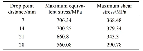
The resulting workpiece stress data for different milling positions are shown in Table 4.
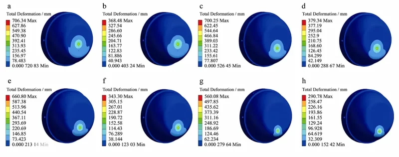
The corresponding deformation contour plots are shown in Figure 5.
Stress and Deformation at Different Cutting Positions
As shown by the simulation results for different turning contact points in Figure 5, the simulation results accurately reflect the stress distribution characteristics under machining conditions;
As indicated by the data in Table 4, the location of the turning tool’s contact point has a significant impact on the local stress levels in the housing.
The cutting tool’s contact point moving from 7 mm to 28 mm away from the center of the housing results in a continuous decrease in the maximum equivalent stress, which drops from 706.34 MPa to 560.08 MPa, representing a reduction of 20.7%.
The maximum shear stress also decreased from the original 368.48 MPa to the current 290.78 MPa, representing a 21.1% decrease.
As shown in the stress distribution contour plot in Figure 5, when the turning tool acts at the 7 mm mark, stress concentration is at its highest, with a relatively large high-stress zone primarily concentrated at the tool contact point and its surrounding area.
This indicates that this location experiences the most severe stress during the turning process and is prone to localized plastic deformation or cutting chatter;
As the contact point moves outward, both the stress peaks and the affected area decrease significantly, and the overall stress distribution across the structure becomes more uniform.
This indicates that the thin-walled sections farther from the center have higher stiffness and stronger resistance to deformation.
Scope and Limitations of the Simulation
This simulation is an equivalent static load analysis;
A coupled thermal-mechanical model for the cutting process was not established, and the transient temperature field and thermal stresses in the cutting zone were not solved.
The simulation is used solely to compare the relative magnitudes of stress distributions at different cutting positions and to identify structural weak points;
It is not intended to calculate the absolute thermal deformation or high-temperature stresses caused by cutting heat.
In actual milling operations, a high-pressure, high-flow cooling system is employed to forcibly cool the workpiece, thereby minimizing the overall temperature rise of the workpiece and reducing the impact of cutting heat on workpiece deformation.
Machining Risk and Feed Strategy
Further analysis combining the quantitative values in Table 4 with the stress contour plot in Figure 5 reveals the following:
1) Stress decreases as the cutting point moves outward, but this decrease exhibits distinct nonlinear characteristics;
The decrease in stress is minimal in the 7–14 mm range, indicating that the central region from 0 to 14 mm is a high-risk cutting zone;
Even slight fluctuations in cutting force within this range can induce high local stresses.
When the cutting point exceeds 14 mm, the rate of stress decrease increases significantly, extending toward the outer shell, and the structure’s ability to resist external loads improves rapidly;
2) The contour plot shows that high stresses are confined solely to the local area of tool contact, representing localized stress concentration that does not propagate throughout the entire shell.
Although the shell as a whole has not reached yield, the local equivalent stress at the central 7 mm position is already close to the yield strength of TC4, posing a risk of localized microplastic deformation.
This is also the underlying reason why contour deviations and dimensional drift frequently occur in the central region of the milled bottom surface during actual machining;
3) These simulation results provide guidance for actual machining feed strategies.
Where process conditions permit, prolonged cutting dwells in the high-risk central region (0–14 mm) should be minimized as much as possible.
Feed paths should be optimized to reduce the duration of sustained cutting loads at the center, thereby mitigating the tendency toward local deformation and chattering.
Cutting Flutter in the Machining of Titanium Alloy Covers
Titanium alloy covers have thin walls and low rigidity, making them prone to cutting flutter during turning.
This not only affects machining accuracy and surface quality but also leads to accelerated tool wear and workpiece scrap.
Analysis of cutting flutter reveals the patterns of vibration response under different cutting parameters and contact positions, identifies flutter-prone conditions, and provides a theoretical basis for process optimization and fixture improvements.
This is of great significance for enhancing the machining stability and yield rate of titanium alloy housings.
The modeling in this chapter does not account for the impact of wall thickness variations caused by hot forming on the distribution of structural stiffness, thereby better reflecting the dynamic characteristics of actual workpieces.
The research is divided into three parts:
First, the natural dynamic characteristics of the unsupported original structure are analyzed using the modal superposition method to identify the structural root causes of chatter;
Second, parametric optimization of the central pusher support scheme is conducted to determine the optimal fixture parameters;
Finally, through dynamic simulations and physical machining experiments, the flutter suppression effectiveness of the optimized solution is systematically verified.
Natural Modal Characteristics of the Original Structure
The modal superposition method is currently the primary method for solving the dynamics of structures under dynamic load excitation.
The core principle of this method lies in the discrete decoupling of structural systems.
It calculates the eigenvalues and eigenvectors corresponding to each order of mode.
Based on the contribution of each mode, structural dynamics under continuous frequency-sweep conditions can be obtained via superposition operation.
This paper takes the natural frequencies and mode characteristics of the titanium alloy enclosure as the basis.
The actual boundary constraints of the structure are also considered.
The system dynamic control equations for the enclosure structure are established accordingly, as shown in Equation (1).

In the equation: M, C, and K represent the equivalent mass, damping, and stiffness matrices of the titanium alloy enclosure structure, respectively; u(t) is the displacement vector; And F(t) is the external force.
Using the finite element method, a modal coordinate transformation is performed on the preset displacements of the titanium alloy enclosure structure in physical space:

In the equation: qi represents the modal coordinates; ϕi represents the natural frequency and mode shape of the titanium alloy housing structural system.
By utilizing the orthogonality of the modal components of the dynamic system, the original kinematic equations can be decoupled into single-degree-of-freedom equations:

In the equation: Mi, Ci, and Ki represent the modal mass, modal damping, and modal stiffness matrices, respectively; Qi(t) represents the generalized force.
Qi(t) is calculated separately for each decoupling equation using the frequency-domain method, and the final physical response is the superposition of the responses of each mode:

Finite Element Modal Analysis Setup
Fixed boundary conditions were applied to the connection brackets of the titanium alloy housing.
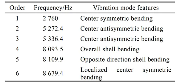
A modal analysis was performed using a mesh model and material parameters consistent with those of the static analysis to obtain the first six natural frequencies of the housing in an unsupported state, with a base support preload of 10 kN.
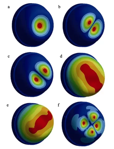
The mode shape contour plot is shown in Figure 6, and the corresponding frequencies and mode shapes are listed in Table 5.
Natural Frequencies and Mode Shape Characteristics
The results show that the first-order natural frequency is 2,760.0 Hz, with a mode shape exhibiting centrally symmetric bending;
The second- and third-order natural frequencies are 5,272.4 Hz and 5,336.4 Hz, respectively, corresponding to two types of centrally antisymmetric bending mode shapes;
The fourth- and fifth-order natural frequencies are 8,093.5 Hz and 8,109.9 Hz, exhibiting characteristics of global bending and anisotropic bending of the shell;
The sixth-order natural frequency is 8,679.4 Hz, with the mode shape being centrally localized symmetric bending.
The low-order modes of the cover are dominated by localized bending in the central region;
As the order increases, the mode shapes gradually extend to the entire shell.
The relatively low first-order natural frequency indicates that the central region has lower stiffness and is a sensitive area for cutting flutter;
The significantly higher frequencies of the higher-order modes correspond to the shell’s higher overall stiffness.
These modal characteristics directly reveal that thin-walled hoods are more prone to vibration during cutting in the central region, providing a basis for subsequent optimization of cutting parameters, design of auxiliary support fixtures, and avoidance of resonance frequencies.
Parametric Optimization of the Central Pivot Support Scheme
To address the issue of insufficient stiffness in the central region of the housing, a recessed central pivot support scheme was designed to enhance overall stiffness by constraining the degrees of freedom at the base of the pivot.
To determine the optimal fixture parameters and avoid subjectivity in parameter selection, parametric simulation comparisons were conducted for the two key parameters—support diameter and support preload.
The optimal scheme was determined by comprehensively evaluating the stiffness improvement and manufacturability.
For the support diameter parameter optimization, six support diameter schemes were set: 0 (no support), 10, 15, 20, 25, and 30 mm.
The preload was uniformly set at 10 kN.
The first-order natural frequencies and machining toolpath interference for each scheme were compared; the results are shown in Table 6.
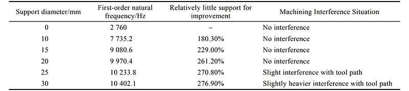
It can be seen that the first-order natural frequency of the housing keeps rising as the support diameter increases, while the growth rate gradually decreases.
The frequency rises stably within the diameter range of 0 mm to 20 mm.
When the diameter increases from 20 mm to 30 mm, the frequency growth rate drops significantly, with a total increase of only 4.3%.
Moreover, tool interference occurs when the diameter exceeds 25 mm, which reduces its engineering application value.
Combining the requirements of stiffness improvement and machinability, 20 mm is preliminarily selected as the optimal support diameter.
This dimension provides sufficient central constraints and prominent stiffness enhancement while completely avoiding machining tool interference.
It achieves the best balance between structural performance and practical application feasibility.
Optimization of Support Preload Parameters
Based on the preliminary selection of a 20 mm support diameter, we further conducted a detailed optimization of the preload.
The preload determines the contact fit of the support surface;
If it is too small, it will result in insufficient contact and inadequate stiffness, while if it is too large, it will introduce additional clamping deformation and affect machining accuracy.
Five sets of preload schemes—5, 8, 12, 15, and 20 kN—were established, and the trends in first-order natural frequency were compared; the results are shown in Table 7.
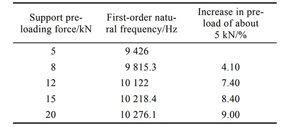
The results show that preload is nonlinearly and positively correlated with the first-order natural frequency, and 12 kN is identified as the performance inflection point.
In the range of 5–12 kN, the increase in preload mainly improves the contact fit of support surfaces, thereby enhancing structural stiffness.
this results in a significant increase in frequency, while the additional clamping deformation remains within a controllable range;
Above 12 kN, the support surfaces are already fully in contact; further increasing the preload has only a negligible effect on stiffness and introduces significant elastic deformation due to clamping, which is detrimental to dimensional accuracy control during finishing.
Determination of the Optimal Support Combination
To eliminate cyclic dependencies among the parameters, the optimized preload of 12 kN was applied to all diameter schemes for verification.
The results show that the first-order natural frequencies of all schemes increased only slightly compared to the 10 kN baseline, and the ranking of diameters in terms of performance fully aligns with the machining interference characteristics;
20 mm remains the optimal choice among the interference-free schemes.
In summary, a support diameter of 20 mm and a preload of 12 kN constitute the globally optimal combination.
Verification of the Dynamic Performance of the Optimized Design and Experimental Results
After adopting the optimized center-support design with a diameter of 20 mm and a preload of 12 kN, simulation comparisons were conducted from two perspectives: modal characteristics and vibration transmission characteristics.
The actual engineering performance of the design was verified through physical machining experiments.
The cloud plot of the first six mode shapes of the optimized cowling is shown in Figure 7, and the corresponding natural frequencies and mode shape characteristics are listed in Table 8.
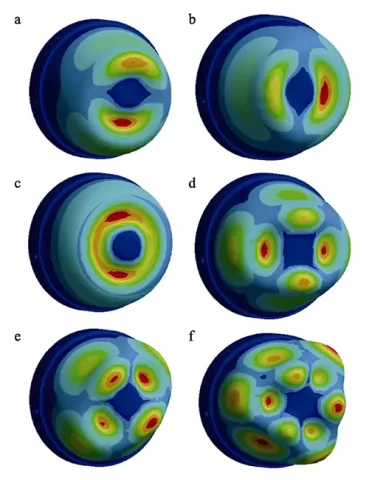
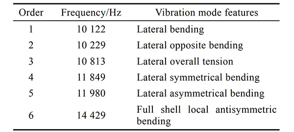
A comparison shows that the central support fundamentally alters the modal characteristics of the housing:
The first-order natural frequency increases from 2,760.0 Hz to 10,122 Hz—a 266.7% increase—and the overall stiffness is significantly enhanced;
The second- and third-order natural frequencies increased by 94.0% and 102.6%, respectively, while the sixth-order natural frequency increased by 66.2%, with frequencies across all orders rising substantially.
The modal characteristics have undergone a fundamental change.
In the original structure, the low-order modes were dominated by localized bending at the center, with stress concentrated in the tool contact area;
After optimization, the modal behavior shifted to global bending along the shell’s sides, completely eliminating the low-stiffness localized modes in the central region.
Stress distribution now spreads uniformly across the shell, structurally eliminating the risk of resonance at the cutting contact point.
Vibration Transmission Analysis and Flutter Suppression Performance
To systematically evaluate the flutter suppression effect, the machine tool’s machining end was used as the excitation input and the connecting block as the vibration output.
The vibration transmission characteristics under excitation in the machining direction were analyzed via simulation, yielding the variation of the transmission ratio with frequency, as shown in Figure 8.
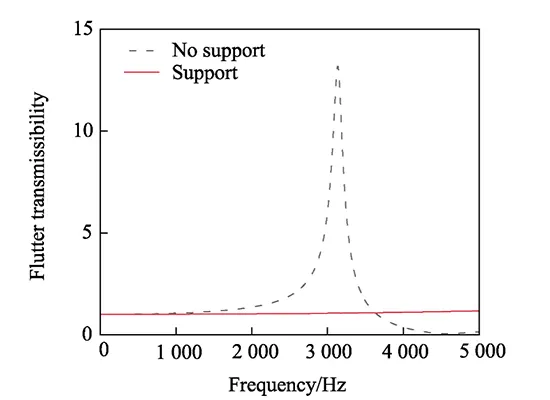
As shown in the graph, the unsupported structure exhibits a significant resonance peak near 3,100 Hz, with a peak transmission ratio as high as 13.2;
The vibrational energy is greatly amplified, making it highly prone to triggering severe cutting flutter;
In contrast, the central support design maintains a vibration transmission ratio consistently below 1.0 across the entire 0–5,000 Hz frequency range.
The curve is flat with no obvious resonance peaks, and the resonance peaks are completely eliminated.
Quantitative comparisons show that the maximum vibration transmission ratio of the optimized structure is 92.4% lower than that of the original structure;
Near the original resonance frequency, the transmission ratio drops sharply from its peak to near 0, representing a reduction of over 99%;
In the original structure, the transmission rate in the 2,500–3,500 Hz range was consistently above 3, indicating a state of vibration amplification;
After optimization, the transmission rate in this range stabilized at 0.8–0.9, with no amplification effect whatsoever.
These results are highly consistent with the conclusions of the modal analysis, confirming that the central support effectively cuts off the transmission path of vibration energy to the workpiece, thereby achieving effective suppression of cutting chatter.
Production Validation and Machining Accuracy Improvement
A statistical analysis of 120 products from the same batch manufactured using the conventional process showed an overall pass rate of 72.5%, with surface contour distortion, uneven wall thickness, and surface chatter caused by cutting flutter being the primary causes of failure.
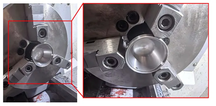
To verify the engineering effectiveness of the optimization scheme described in this paper, a validation batch was machined under identical production conditions; the physical samples are shown in Figure 9.
A total of 120 parts were produced in this validation batch, with 113 passing inspection.
A coordinate measuring machine (CMM) was used to measure the flatness of the bottom surface and the surface profile, while a vibration accelerometer was used to record the vibration amplitude during the cutting process.
The simulation predictions were compared with the measured average values, and the results are shown in Table 9.
The comparison of experimental data with simulation data is shown in Figure 10.
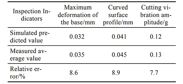
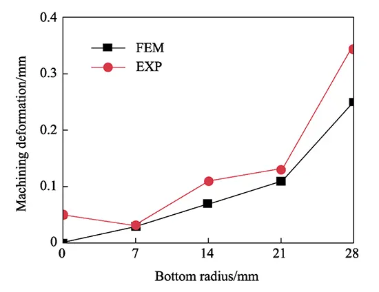
The results show that the relative errors between the simulation and actual measurement values for all indicators were less than 10%, falling within an acceptable engineering range, thereby validating the accuracy of the finite element model and the reliability of the optimization scheme.
Batch production statistical results verify the effectiveness of the proposed full-process optimization scheme.
After the scheme was implemented, the product yield was significantly improved.
Specifically, the yield rate rose from 72.5% under the original processing method to 94.2%.
This improvement fully satisfies the machining accuracy and stability requirements for thin-walled curved titanium alloy housings.
Conclusion and Outlook
This paper addresses the issues of machining deformation and flutter in the milling process of thin-walled, curved TC4 titanium alloy shrouds used for aircraft engine protection.
It analyzes the mechanism of deformation inheritance resulting from the preceding hot forming process (limited to theoretical analysis; No hot forming simulation tests were conducted) and conducts a systematic study through finite element simulations of milling conditions and physical milling experiments on raw blanks.
The main conclusions of this study are as follows:
Optimization of Clamping Parameters and Deformation Control
The clamping pressure exhibits a strictly linear positive correlation with the shroud’s displacement and stress.
Under a clamping load of 30 MPa, the yield safety factor is 1.22, which falls within the reasonable range for clamping thin-walled aerospace components.
This setting simultaneously satisfies the requirements for strength safety and clamping stiffness, making it the optimal clamping parameter.
The turning forces decrease as the contact point moves away from the center;
From 7 mm from the center to 28 mm at the outer edge, the maximum equivalent stress and maximum shear stress decrease by 20.7% and 21.1%, respectively.
The bottom center is the area with the weakest structural stiffness and the most severe cutting forces.
Chatter Suppression Through Structural Optimization
Central pin support significantly improves structural dynamic characteristics.
The optimized parameter solution adopts a support diameter of 20 mm and a preload of 12 kN.
This optimal scheme improves the first-order natural frequency by 266.7%.
Meanwhile, the peak vibration transmission rate is reduced by more than 92.4%.
Such significant performance improvements eliminate the risk of low-order resonance and greatly suppress cutting chatter.
Production Validation and Future Development
The full-process optimization scheme was implemented in production.
The batch pass rate of products increased from 72.5% to 94.2%.
The relative errors between simulation and measured results were below 10% for all indicators.
These outcomes verify the reliability and engineering practicality of the proposed scheme.
In the future, further consideration can be given to the impact of thermal-mechanical coupling during cutting on deformation.
By integrating online monitoring technology to enable dynamic, adaptive adjustments to machining parameters, the machining accuracy and stability of thin-walled titanium alloy parts can be further improved.