
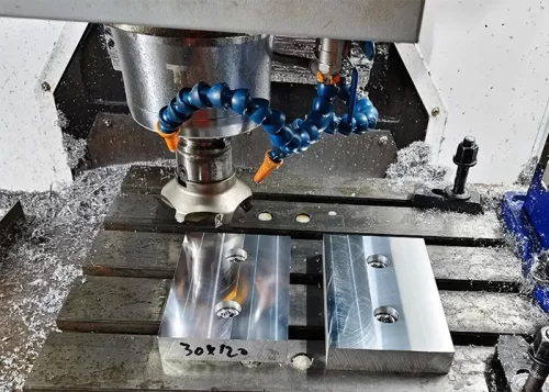





In recent years, with the rapid development of the manufacturing industry, the focus has increasingly shifted toward high precision and high efficiency.
Under these circumstances, the importance of improving the quality and efficiency of machining multi-faceted parts is self-evident.
Practical experience has shown that multi-surface parts feature complex structures and demand high machining accuracy.
This necessitates a tightly coordinated machining process, thereby placing higher demands on the machining capabilities of CNC milling machines.
Currently, researchers largely limit CNC milling machine research to specific technical aspects, and they have not established systematic machining specifications.
Therefore, conducting relevant research holds significant practical importance for preventing the occurrence of typical problems in production practice.
Process Characteristics and Technical Challenges of CNC Milling for Multi-Faced Parts
Structural Characteristics and Precision Requirements of Multi-Faced Parts
1. Machining Characteristics of Multi-faced Parts
Due to the complexity of their structures and the significant machining difficulties involved, multi-faced parts place even more stringent demands on machining technology.
Typically, manufacturers produce multi-faced parts in small batches, so machinists must ensure actual machined dimensions strictly conform to the specifications outlined in the drawings during machining.
Furthermore, in addition to dimensional accuracy, the machined surfaces of the parts must be free of defects such as scratches and scuffs.
Even more strictly, if defects do occur, operators must not repair the workpiece surface during machining with materials such as sandpaper or files.
Additionally, compared to machining standard parts, the machining processes for multi-surface parts are more complex and involve more machining operations.
This necessitates repeated clamping and positioning during machining, further increasing the difficulty of part machining.
2. Datum Conversion in Multi-surface CNC Milling
In the end-to-end process of CNC milling for multi-surface parts, clamping and positioning serve as the critical factors determining the success or failure of machining.
Multi-surface machining differs fundamentally from single-surface machining.
After the machining of a single surface, workpiece flipping and repositioning are essential for subsequent manufacturing procedures.
This process inevitably produces reference transformation, which refers to the offset between the initial machining datum and the subsequent datum.
Such datum conversion serves as a necessary precondition for machining the residual surfaces of the workpiece.
In theory, an ideal reference transformation should achieve zero error; however, in practical applications, each re-clamping introduces “repeatability errors.”
3. Sources and Cumulative Effect of Re-clamping Errors
These errors originate from several sources. They contain inherent manufacturing deviations of the fixture.
Clearance exists between the locating surfaces of the workpiece and the locating elements of the fixture.
Clamping force induces elastic deformation of the workpiece.
Residual chips or foreign contaminants on the workpiece surface also contribute to errors.
Such errors are cumulative and latent in nature.
For example, when machining a cubic part, the bottom surface is machined first, followed by the side surfaces using the bottom surface as a reference, and finally the top surface using the side surfaces as a reference;
A perpendicularity deviation of 0.01 mm may exist between the bottom face and side faces.
Geometric relationships can amplify this 0.01 mm deviation.
As a result, the parallelism error of the top face with respect to the bottom face may exceed 0.03 mm or become even larger.
The Complexity of Clamping and Positioning and the Control of Repeatability Errors
1. Contradiction Between Process Consolidation and Datum Consistency
In modern CNC machining, to achieve efficiency gains, there is a widespread trend toward process consolidation—that is, completing as many surface machining operations as possible during a single setup on a single CNC milling machine;
The manufacturing process for multi-surface parts often requires the integration of heterogeneous operations such as milling, drilling, reaming, reaming, boring, and tapping, with tool sizes varying significantly.
This situation directly gives rise to a structural conflict between “process integration” and “reference point consistency.”
2. Geometric Error Transmission of Rotary Indexing
To cover all surfaces to be machined, operators must rotate or index the workpiece; this requirement imposes specific demands on the indexing accuracy of the machine tool table and the fourth axis.
Workpiece rotation changes the spatial geometric mapping relationship between the workpiece coordinate origin and the machine tool coordinate origin.
Therefore, engineers must accurately calculate this geometric relationship in advance.
Operators then import the calculated parameters into the CNC system for subsequent machining.
In this process, zero-point offsets and backlash errors of all rotational axes affect the positional accuracy of the machined surfaces.
3. Collision Risk and Workpiece Deformation Challenges
Engineers must also address the risk of tool interference, another critical issue.
Specifically, when machining surface A, the tool and toolholder assembly may come into spatial conflict with the fixture used to position surface B.
This requires the fixture design to be extremely compact and capable of maneuvering within the machining space to avoid collisions;
However, these design constraints, in turn, limit the fixture’s rigidity reserve and positioning stability.
Multi-surface workpieces generally reserve a certain machining allowance.
Therefore, the process requires high cutting forces and large clamping forces in rough machining.
Such loads readily induce geometric deformation of the workpiece.
It is critical to achieve a dynamic balance between process stability and reference system conversion in multi-surface machining.
Maintaining continuous consistency and high precision of the workpiece reference system throughout the machining process is essential.
This poses a core challenge for the process planning of thin-walled curved component machining and requires focused attention.
Challenges in Multi-Process Integration and Unification of Machining Reference Systems
In response to the aforementioned technical bottlenecks, the implementation of systematic technical interventions has become an absolute necessity.
High-precision machining requires systematic and multi-dimensional optimization interventions.
Such interventions cover multiple key technical dimensions, including fixture structure design, CNC programming strategy optimization, and suppression of geometric and positional deviations.
These integrated improvements help construct a complete end-to-end guarantee system for high-precision machining.
Iterative optimization of clamping strategies serves as the core guarantee for controlling machining deviations of multi-surface parts.
This optimization strategy focuses on three key objectives.
These include reducing clamping times, improving positioning stiffness, and eliminating errors induced by reference transformation.
Researchers and manufacturers must urgently advance the large-scale application of combination fixtures and flexible fixture systems.
For multi-sided parts produced in small-to-medium batches with a wide variety of configurations, traditional dedicated fixtures suffer from high manufacturing costs, lengthy lead times, and a lack of versatility;
The adoption of combination fixtures featuring hole or slot systems allows for the rapid integration of standard components to meet the positioning requirements of parts with diverse geometric contours.
Manufacturers have widely applied modern flexible fixtures in precision machining, including hydraulic self-centering center frames, vacuum suction fixtures, and multi-point floating support fixtures.
These advanced fixture types support rapid positioning and clamping of workpieces.
They effectively shorten auxiliary processing time and improve overall machining efficiency.
For polyhedral parts, the flexible application of the six-point positioning principle guides the design of multi-surface positioning devices and interlocking clamping mechanisms.
This technical approach eliminates component-force-induced workpiece deformation and maintains reasonable clamping force levels during operation.
Key Technical Measures for High-Precision Multi-Surface Machining on CNC Milling Machines
Optimization of Clamping Strategies and Application of Multi-Surface Positioning Technology
1. Core Idea: Single-setup Fixture Design Based on Process Concentration
Optimizing clamping strategies is the primary step in controlling machining deviations during the machining of multi-surface parts.
In practical applications, technicians prioritize the principle of process concentration to address the challenges of frequent workpiece rotation and reference point changes in high-precision multi-surface machining.
This involves designing specialized or modular fixtures capable of completing multi-surface machining in a single setup.
In practical implementation, technicians apply the six-point positioning principle to select optimal positioning references according to the characteristics of different machined surfaces.
For box-shaped and complex polyhedral components, engineers require highly optimized positioning and clamping schemes.
Manufacturers can widely adopt the “one-plane two-pin” positioning method alongside hydraulic self-locking and pneumatic multi-point interlocking fixtures.
2. Unified Datum Calibration for Workpiece Flipping and Repositioning
When turning the workpiece over for machining, technicians must establish a unified process reference system.
Operators can perform inter-process origin calibration using a precision coordinate measuring machine (CMM).
Alternatively, technicians can employ fixtures integrated with high-precision optical positioning systems.
These technical methods achieve zero-deviation datum alignment after workpiece flipping and repositioning.
3. Flexible Clamping and FEA-Assisted Clamping Force Optimization
The introduction of flexible clamping technology is also a key measure and plays a significant role in workpiece machining.
Multi-point vacuum suction cups or magnetic fixtures can replace conventional clamping plates in precision machining.
This alternative clamping method maximizes the exposure of workpiece machined surfaces.
It effectively reduces tool interference risks and simplifies the design of tool avoidance paths.
Furthermore, it provides favorable conditions for the planning of sophisticated and complex cutting trajectories.
For thin-walled, multi-faceted parts prone to deformation, the use of internal supports or conformal fixtures is essential.
The incorporation of finite element analysis (FEA) simulations into clamping strategies allows for the pre-optimization of clamping force magnitude and application points.
This optimization process aims to prevent workpiece deformation caused by the release of clamping stresses.
The uniformity of machining allowances across all surfaces and the high-precision achievement of final geometric and positional tolerances are the shared objectives of this series of measures.
Improving the Modular Design of CNC Programs
1. Modular Hierarchical Architecture of CNC Programs
As the core instruction set that governs machine tool motion trajectories, well-structured CNC programming is critical to guaranteeing the machining accuracy and efficiency of multi-surface components.
Considering the inherent characteristics of multi-surface machining, including cross-process interleaving and frequent tool switching, modular and hierarchical design philosophies are essential for developing robust and reliable CNC programs.
A nested architecture consisting of main programs and independent subprograms can be established to decompose the overall machining procedure into multiple standardized functional units, such as rough machining modules, finish machining modules, drilling modules, and tool change modules corresponding to different feature surfaces.
In the main program framework, conditional judgment statements and process scheduling instructions, such as the M98 subprogram calling command, are adopted to activate individual functional modules in accordance with the predefined machining sequence.
This modular hierarchical structure provides distinct logical clarity and facilitates program debugging, modification, and maintenance.
When the machining allowance or geometric parameters of a specific surface are updated, only the corresponding subprogram requires local revision, rather than rewriting the entire CNC program.
2. Macro Programming for Complex Geometric Feature Adaptation
Furthermore, variable programming and macro programming techniques enable efficient logical processing of complex geometric features commonly found in multi-surface parts, including arrayed hole groups, uniformly distributed grooves, and mathematically defined curved profiles.
Equipped with built-in arithmetic, logical, and loop control functions, macro programming can effectively reduce program redundancy and improve overall programming efficiency.
In addition, macro programming exhibits excellent parameter adaptability.
When the dimensional benchmarks of a target component change, merely adjusting the initial variable parameters enables the program to adapt to the updated machining requirements automatically.
This mechanism avoids repeated program rewriting and eliminates potential coding errors introduced during conventional program regeneration.
3. Toolpath Optimization, Collision Verification and Cutting Parameter Control
The optimized configuration of toolpaths and the verification of collision avoidance mechanisms are core priorities in program design.
In multi-surface machining scenarios, the continuous dynamic changes in workpiece orientation make the risk of interference between the tool, toolholder, fixture, and the machine tool’s axes highly likely.
In the programming stage, the advanced simulation modules embedded in CAM software can be fully utilized to conduct comprehensive collision detection.
Combined with the optimization and fine adjustment of tool entry and exit trajectories, this method ensures safe and efficient tool movement.
It guarantees that the tool follows the shortest feasible path during non-cutting strokes while avoiding potential collisions.
Vector control of the cutting spindle in five-axis machining must be strictly enforced.
The core objective is to avoid collisions between the tool shank and the workpiece or fixture.
The optimized selection of cutting parameters must be embodied within the program structure;
For heterogeneous materials, different tool configurations, and distinct machining stages (including roughing and finishing), the program should preload sets of optimal parameters for feed rate, spindle speed, and cutting depth;
Corner transition zones and tool entry/exit positions are vulnerable to abrupt load fluctuations during machining.
Enabling the automatic feed rate adjustment function in CNC programs can effectively mitigate such sudden load variations.
This strategy prevents tool chipping and workpiece overcutting, thereby stabilizing the machining accuracy of components.
Application of Machining Process Error Compensation Mechanisms
1. Compensation for Machine Tool Geometric Deviations and Backlash
Even after optimizing fixture configuration and employing high-precision programs, inherent geometric deviations of the machine tool, thermal distortion, and structural displacement induced by cutting forces can still cause actual machined dimensions to deviate from theoretical set values.
Therefore, establishing a comprehensive machining error compensation framework that covers the entire process is the only viable path to achieving ultra-precision multi-surface machining.
The foundation of this framework lies in compensating for machine tool geometric deviations and backlash. Most CNC systems are equipped with pitch error compensation and backlash compensation modules.
Prior to activating functional compensation modules, the positioning accuracy of each machine tool axis should be fully calibrated via ultra-precision measuring equipment such as laser interferometers.
The collected deviation data of each coordinate node can then be imported into the CNC system to update the compensation matrix.
This corrects cumulative pitch errors in the leadscrews and backlash in the drive train, thereby improving the machine tool’s positioning accuracy;
For five-axis machine tools, calibration and compensation of the tool center point (TCP) on the rotary axis must also be performed.
2. Data-Driven Thermal Distortion Compensation and Mechanical Model Simplification
1) Data-Driven Real-Time Compensation for Thermal Geometric Distortion
Additionally, compensation for thermal geometric distortion is one of the key methods for machining process compensation.
Prolonged continuous machining induces motor heat generation, cutting heat flux and ambient temperature fluctuations.
These factors trigger microscale thermal expansion of the machine tool structure and degrade the relative positional accuracy of multi-surface parts.
To tackle this problem, a data-driven machining error compensation model can be constructed.
This model incorporates the predicted elastic tool clearance error and the comprehensive machining error derived from measured data.
Specifically, a thermal deviation compensation module is designed within the CNC system, and temperature sensors are installed at key heat-sensitive locations on the machine tool.
By combining real-time temperature data with a preset deviation model, the system automatically performs real-time compensation for the coordinate axes.
2) Simplification of Mechanical Models for Thin-Walled Blade Deformation Analysis
Even when the mechanisms of cutting mechanics are understood and a stress analysis model has been constructed, assumptions regarding material continuity, geometric isotropy, and small deformations under loading can still cause mechanical calculation results to deviate from the workpiece’s actual shape.
Therefore, establishing simplification principles for mechanical models based on typical components is a necessary prerequisite for the qualitative analysis of blade cutting deformation.
The core of this principle is to simplify complex thin-walled structures into beam or thin-plate models. Traditional mechanical analysis often faces analytical challenges due to structural complexity.
The simplification of mechanical models requires standardized preprocessing operations.
First, secondary geometric features are eliminated following fundamental material mechanics principles.
Subsequently, a simply supported beam model with key contour and cross-sectional parameters is constructed.
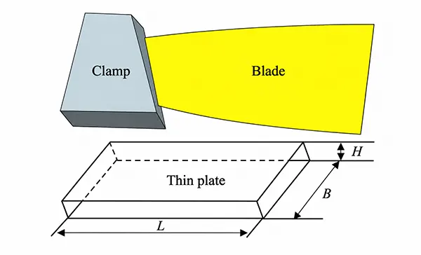
This approach simplifies the irregular blade structure into a standard regular geometry for mechanical analysis.
This approach circumvents the difficulties in obtaining analytical solutions and qualitatively reveals the elastic tool-yielding behavior induced by cutting forces.
For aircraft engine blades, it is also necessary to map the external dimensions to the characteristic parameters H, B, and L, as shown in Figure 1.
3. On-machine Measurement and Counter-Compensation for Random Machining Errors
Once the planar machining is complete, a probe can be used to measure the actual spatial positions of the aforementioned planes.
During this process, if the measured results deviate from the theoretical design by ≥ 0.02 mm, a 0.02 mm counter-compensation must be applied during the subsequent machining of another plane.
This method can eliminate random errors induced by clamping stress deformation, gradual tool wear and machine tool thermal drift.
Consequently, the machining accuracy of all geometric features on multi-surface parts can fully satisfy the requirements of engineering drawings.
Conclusion
The CNC milling process for multi-surface parts has a direct impact on machining accuracy and quality.
This requires companies to strengthen training for CNC machinists, equipping them with the ability to select appropriate CNC milling processes, conduct comprehensive process analyses, and flexibly design machining solutions for multi-surface parts.
When machining parts using CNC milling machines, machinists must select the correct fixtures and continuously improve machining techniques to ensure that CNC machines can enhance both machining efficiency and quality when processing special parts.