





The numerous machining features, high geometric accuracy requirements, and thin-walled areas prone to deformation are all challenges encountered during the machining of parts.
How to address these machining challenges has become a focal point of research for many scholars.
Wei Juan et al. analyzed the structural features of shell parts and studied machining techniques from the perspectives of clamping methods, machining processes, and toolpaths for different features;
Yang Yang et al. analyzed the structure and manufacturing processes of air rudder parts.
They also investigated CNC machining technologies.
Their research covered machining processes, specialized fixtures, and programming methods.
Wang Jixiong et al. analyzed the structural characteristics of thin-walled aircraft support parts.
On this basis, the team designed specialized machining fixtures and optimized the corresponding machining processes.
These effective measures reduced the accumulation of machining errors and further improved the surface quality of workpieces.
This study primarily aims to improve part positional accuracy and dimensional accuracy, as well as to address the issue of deformation in thin-walled parts.
Part Structural Analysis
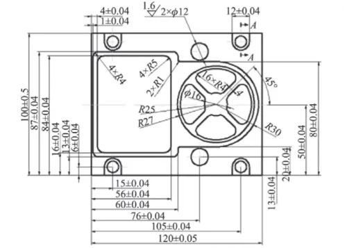
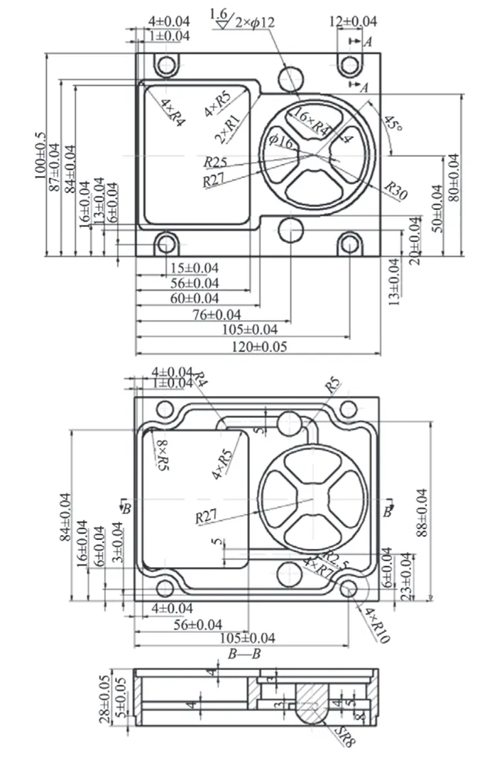
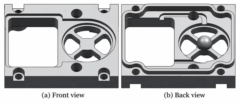
The part drawing and 3D model of the heat sink are shown in Figures 1 and 2, respectively.
We can combine these two figures to analyze the structural features of the part.
The main features of the part include through holes, sector-shaped cavities, circular cavities, and rectangular cavities.
They also cover flat surfaces, curved surfaces, hemispherical surfaces, fillets, flow channels, and U-shaped grooves.
As shown in Figure 2, both the front (Figure 2a) and back (Figure 2b) of the part feature machining elements. The part has a complex structure and requires high positional accuracy.
Its outline dimensions are 120 mm × 100 mm × 28 mm, and it is made of aluminum alloy.
Machining Specifications for the Part: Dimensions not specified have a tolerance of IT13.
The part has four φ8 mm through-holes and two φ12 mm through-holes; specific dimensions are shown in Figure 1.
Analysis of Part Machining Processes
Analysis of Machining Challenges
1. Difficulty in Ensuring Positional Accuracy
Since both the front and back surfaces of the part have features that require machining, traditional fixture plates require multiple clamping operations.
Repeated clamping leads to the accumulation of positional accuracy errors, causing deviations in the machining positions on both sides of the part.
Additionally, clamping plates stop operators from completing machining on certain areas of the part in a single operation, lowering machining efficiency during batch production.
Therefore, it is necessary to design a specialized fixture with positioning capabilities.
Operators should select two suitable feature holes on the part as positioning holes for each clamping operation to ensure the part’s positional accuracy.
2. Thin-walled Parts Are Prone to Deformation
The part’s thin-walled sections have wall thickness ranging from 1 mm minimum to 4 mm maximum, and machinists must remove a significant amount of material from all sections.
As machinists remove large quantities of material, the combination of cutting forces and substantial cutting heat can easily deform the thin-walled areas.
Large-scale material removal from the part interior reduces the overall rigidity of the workpiece.
The resulting thin walls are highly prone to deformation under tool cutting forces.
This deformation negatively affects the final machining accuracy of the part.
Engineers must take these factors into account when designing specialized fixtures to suppress deformation of the part’s thin-walled sections.
Tool Selection
Machinists perform multiple machining operations on heat sink components, including milling, drilling, reaming, tapping, and chamfering; therefore, they need several cutting tools.
Considering the characteristics of the component material, engineers select carbide cutting tools.
Engineers select the cutting tools appropriately after comprehensively evaluating the heat sink component dimensions and machining requirements.
The tool selection is shown in Table 1.
| No. | Tool Name | Tool No. | Diameter (mm) | Length (mm) | Cutting Edge Length (mm) |
|---|---|---|---|---|---|
| 1 | Drill Bit | T01 | 10 | 75 | 35 |
| 2 | Reamer | T02 | 11.5 | 70 | 35 |
| 3 | Reaming Tool | T03 | 12 | 75 | 35 |
| 4 | End Mill | T04 | 20 | 75 | 45 |
| 5 | End Mill | T05 | 8 | 65 | 40 |
| 6 | End Mill | T06 | 10 | 45 | 45 |
| 7 | End Mill | T07 | 3 | 60 | 30 |
| 8 | End Mill | T08 | 6 | 70 | 30 |
| 9 | Ball Nose End Mill | T09 | 4 | 65 | 25 |
| 10 | Center Drill | T10 | 2.5 | 60 | 20 |
| 11 | Twist Drill | T11 | 8 | 65 | 35 |
Table 1. Tool List
Machining Process Planning
Develop a more efficient machining plan based on the part’s structural features.
Since machinists need to machine features on both the front and back sides of the part, they require multiple setups.
To ensure the relative positional accuracy of the part, high-precision positioning is necessary.
For the first clamping operation, machinists must pre-machine two φ12 mm through holes in the blank to serve as locating holes.
As shown in Figure 1, the surface roughness of the φ12 mm through holes is Ra 1.6 μm;
Machinists machine these locating holes using a drill-ream-tap process;
Analysis shows engineers have clearly defined the machining tasks for the second clamping.
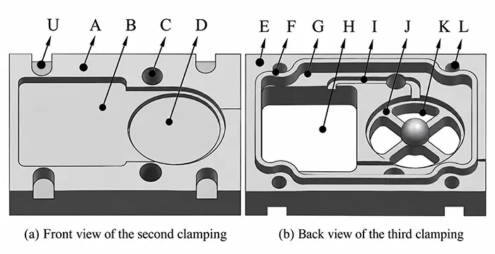
This stage requires the completion of rough machining, semi-finishing, and finishing for Areas A, B, and D, as well as the U-shaped groove on the part’s front face shown in Figure 3a.
The machined surface formed in this process will act as the reference plane for the third clamping operation.
The third setup corresponds to another batch of machining procedures.
It requires full rough machining, semi-finishing, and finishing of areas E, F, G, H, I, J, and the K-shaped sector on the part’s reverse side, as shown in Figure 3b.
In addition, four L4 φ8 mm holes need to be fully machined in this working stage.
The blank dimensions of the workpiece are 130 mm × 110 mm × 30 mm.
As shown in Figure 3, letters mark the areas that machinists will machine during the second and third setups; Table 2 lists the specific machining steps.
| Step | Machining Operation | Tool No. | Tool Size | Feed Rate (mm/min) | Spindle Speed (r/min) | Depth of Cut (mm) |
|---|---|---|---|---|---|---|
| First Setup — Machining Ø12 Locating Hole | ||||||
| 1 | Drilling | T01 | Ø10 | 300 | 2,500 | — |
| 2 | Hole Enlarging | T02 | Ø11.5 | 200 | 1,200 | — |
| 3 | Reaming | T03 | Ø12 | 500 | 1,200 | — |
| Second Setup — Front Side Facing Up | ||||||
| 4 | Rough Milling A, B, C, U | T04 | Ø20 | 800 | 2,500 | 1.5 |
| 5 | Semi-Finish Milling A, B, C, U | T07 | Ø8 | 1,000 | 3,000 | 0.5 |
| 6 | Finish Milling A, B, C, U | T07 | Ø8 | 1,500 | 3,500 | 0.1 |
| 7 | Edge Chamfering and Deburring | T08 | Ø6 | 1,000 | 3,000 | — |
| Third Setup — Reverse Side Facing Up | ||||||
| 8 | Rough Milling D, E, F, G, H, I, J, K | T06 | Ø10 | 800 | 2,500 | 1.5 |
| 9 | Rough Milling M Flow Channel Groove | T05 | Ø3 | 800 | 2,500 | 0.8 |
| 10 | Finish Milling M Flow Channel Groove | T05 | Ø3 | 1,000 | 3,000 | 0.2 |
| 11 | Semi-Finish Milling D, E, F, G, H, I, J, K | T08 | Ø6 | 1,000 | 3,000 | 0.5 |
| 12 | Finish Milling D, E, F, G, H, I, J, K | T08 | Ø6 | 1,000 | 3,000 | 0.1 |
| 13 | Finish Milling Hemispherical Surface | T09 | R2 | 1,500 | 3,500 | 0.1 |
| 14 | Drilling Center Hole | T10 | Ø2.5 | 100 | 2,000 | — |
| 15 | Machining Four Through Holes | T11 | Ø8 | 200 | 2,500 | — |
| 16 | Edge Chamfering and Deburring | T08 | Ø6 | 1,000 | 3,000 | — |
| Fourth Setup — Front Side Facing Up; Dowel-Pin Positioning for Outer-Contour Machining | ||||||
| 17 | Rough Milling Outer Contour | T04 | Ø20 |
Table 2. Machining Process Card
Design of a Custom Fixture
1. Challenges of Traditional Fixture Plate Clamping
This part is produced in batches.
Traditional clamping on a fixture plate is not only inconvenient but also fails to address the issue of deformation in thin-walled parts, making it difficult to ensure the part’s positional accuracy.
By analyzing and planning the machining process, researchers designed a custom fixture to resolve practical processing issues, with improvements focused on the following aspects:
(1) Convenient clamping.
(2) Ensuring part positioning accuracy.
(3) Preventing deformation of the part after clamping, or ensuring that any deformation is minimal and does not affect machining accuracy.
(4) Ensuring that the clamping force of the fixture can offset or reduce the effect of milling forces on the deformation of the part’s thin walls, thereby ensuring that the part’s dimensional tolerances and accuracy meet requirements.
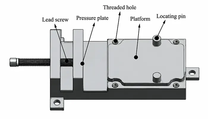
2. Positioning and Clamping Scheme for the First Three Machining Setups
As shown in Figure 2 (part modeling diagram), both surfaces of the part require machining.
Two locating pins are designed to correspond to the two 12-mm-diameter locating holes machined during the first clamping operation;
Their height is lower than the machined surface on the opposite side, and they also serve as clamping devices, with strength that meets the requirements.
For the second and third clamping operations, technicians can adopt a two-pin single-side positioning method to meet positional accuracy requirements.
The fixture generates clamping force by using a lead screw to drive a clamping plate toward the locating pins.
The clamping plate offers two advantages:
First, it generates clamping force and ensures that the force from the lead screw is evenly distributed across the part’s contour surface, preventing deformation caused by localized stress concentration.
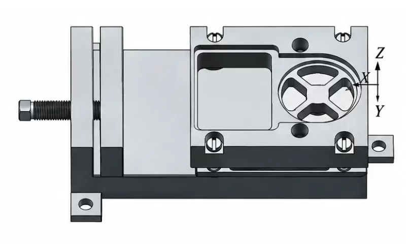
Second, during milling of the H area, it prevents thin-walled sections from deforming outward, as shown in Figures 5 and 6.
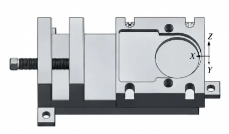
3. Special Rigidity Reinforcement Design for the Fourth Clamping Setup
The fourth clamping operation is intended to complete the roughing, semi-finishing, and finishing of the part’s outer contour.
At this stage, the part is no longer clamped using a lead screw and clamping plate, but rather with pins, as shown in Figure 7.
Because machinists have finished the part’s internal machining, the workpiece is now hollow, which reduces its rigidity.
As a result, the thin-walled sections are highly susceptible to deformation during machining of the external contour.
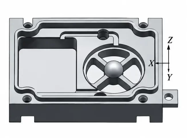
Therefore, engineers designed a boss to mate with the internal contour on the opposite side and increase the part’s rigidity.
The boss section of the fixture is shown in Figure 4.
The Effect of Milling Forces on Part Deformation Under Different Clamping Fixtures
Milling Force Calculation
1. Finite element simulation setup for different clamping fixtures
A comparison was made between clamping using a traditional fixture plate and clamping using a specialized fixture.
Under identical milling force conditions, finite element software was used to analyze the deformation of thin-walled parts under different clamping conditions.
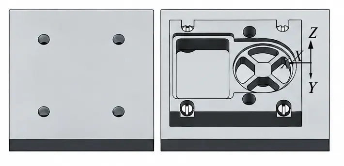
Figure 7 shows machining of the workpiece’s outer contour using a specialized fixture, while Figure 8 shows machining using a traditional fixture plate.
2. Establishment and linear transformation of milling force calculation formulas
Formula for Calculating Milling Forces:

In the equation: C is the material milling condition coefficient, v is the milling speed, ap is the milling depth, f is the feed rate, aw is the milling width, and d is the tool diameter.
By taking the logarithm of both sides of Equation (1) and converting the equation into a linear equation, we obtain Equation (2):

After transforming the data using a four-variable linear model, the linear regression equation is:

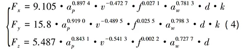
Through data regression analysis of the literature, we can derive exponential formulas for the component forces of the milling force in the x, y, and z directions:
4. Parameter substitution and calculation of actual constraint force
During the actual machining process, thin-walled sections of parts are highly prone to deformation during semi-finishing of the outer contour.
For both fixture clamping methods, the cutting depth (ap) for semi-finishing the outer contour is 23 mm, and the feed rate (f) is 800 mm/min. milling speed v = 78 m/min, milling width aw = 1.5 mm, and tool diameter d = 20 mm.
Since the coolant is not activated, k is taken as 1. Substituting these values into Equation (4) yields Fx = 632.74 N, Fy = 944.36 N, and Fz = 162.46 N.
Theoretically, the cutting forces and theoretical constraint forces must achieve static equilibrium;
However, engineers must multiply the milling force calculation formula by a safety factor K during actual machining. The actual constraint force formula is:

In the formula: the basic safety factor for aluminum alloy materials K0 = 1.5, the machinability factor K1 = 1.2, the tool dullness factor K2 = 1.3, and the cutting characteristics factor K3 = 1.0;
The aluminum alloy cutting coefficient CF = 167, the correction factor kF = 1.0, ae = 0.05d = 1 mm, the feed per tooth af = 0.08 mm, the tool diameter d = 20 mm, the number of teeth z = 4, and the cutting depth ap = 23 mm.
Substituting these values into Equation (5) yields an actual constraint force of 460.18 N.
Finite Element Analysis
Engineers used equations to calculate the component forces of the milling force in the x, y, and z directions at the thin-walled section.
Finite element software was used to analyze the deformation of the thin-walled section when secured by a conventional fixture plate versus a specialized fixture under identical milling force conditions.
After researchers define the material properties, generate the mesh, and apply loads and constraints to the heat sink component within the finite element software, they obtain the solution.
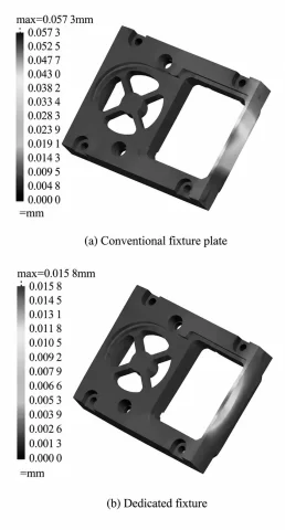
The results are shown in the deformation contour plot in Figure 9.
When technicians clamped the component with a conventional fixture, they measured a maximum deformation of 0.0573 mm, which exceeds the tolerance requirements;
Whereas when clamped using a specialized fixture, the maximum deformation was 0.0158 mm, meeting the tolerance requirements.
VERICUT Machining Simulation Experiment
Part Machining Simulation
Create a new project, define the machining stations, and select the control system and CNC machining center corresponding to the laboratory’s DMG50 CNC machining center.
Import the fixture, workpiece blank, part design model, establish the workpiece coordinate system, and import the cutting tools and machining program in sequence.
After completing the above steps, begin the part simulation machining experiment.
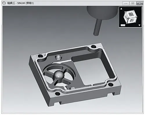
The simulation results are shown in Figure 10.
This process can identify issues such as overcutting, material residue, and collisions during part machining, allowing technicians to make timely corrections.
Part Accuracy Inspection
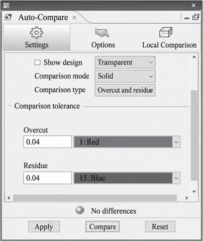
The automatic comparison function is used to inspect part accuracy.
After completing the simulation machining test, the machined part is compared and analyzed against the part design model.
Over-machined areas are displayed in light gray with a comparison tolerance set to 0.04 mm, while under-machined areas are displayed in dark gray with a comparison tolerance also set to 0.04 mm.
The analysis results obtained from this comparison are shown in Figure 11; no differences were found.
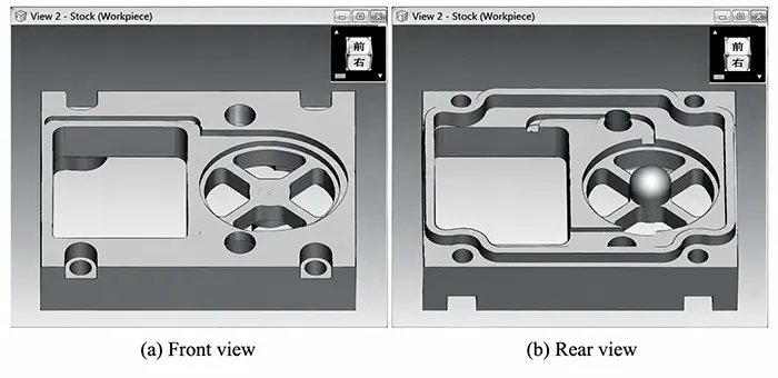
The result of the solid comparison mode is shown in Figure 12.
The specified colors do not appear—there are neither over-machined areas nor under-machined areas—and the part meets the precision requirements.
Actual Machining Experiment
This experiment will use a DMG50 CNC machining center to machine the parts.
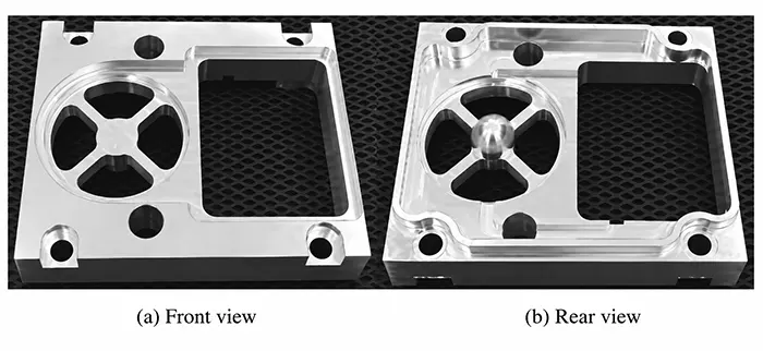
A physical specimen of the heat sink part is shown in Figure 13.
A Hexagon coordinate measuring machine was used to inspect the dimensional accuracy of the part; the inspection results are shown in Table 3.
| Basic Dimension | Measured Dimension | Tolerance | Deviation | Conforms |
|---|---|---|---|---|
| 100 | 100.035 | ±0.05 | +0.035 | Yes |
| 120 | 120.032 | ±0.05 | +0.032 | Yes |
| 28 | 28.029 | ±0.05 | +0.029 | Yes |
| 87 | 87.030 | ±0.04 | +0.030 | Yes |
| 84 | 84.032 | ±0.04 | +0.032 | Yes |
| 105 | 105.029 | ±0.04 | +0.029 | Yes |
| 76 | 76.031 | ±0.04 | +0.035 | Yes |
| 60 | 59.980 | ±0.04 | −0.020 | Yes |
| 16 | 16.032 | ±0.04 | +0.032 | Yes |
| 20 | 20.028 | ±0.04 | +0.028 | Yes |
| 15 | 15.025 | ±0.04 | +0.025 | Yes |
| 13 | 13.027 | ±0.04 | +0.027 | Yes |
| 1 | 1.024 | ±0.04 | +0.024 | Yes |
| 4 | 3.979 | ±0.04 | −0.021 | Yes |
Table 3. Dimensional Measurement
During the machining process, the use of a “one-face, two-pin” positioning method improved the part’s positional accuracy.
During the third clamping, the fixture’s clamping plate prevented the thin-walled section from deforming outward, and during the fourth clamping, the fixture’s boss prevented the thin-walled section from deforming inward;
These measures played a crucial role in improving the part’s machining accuracy.
The dimensional accuracy measurement data verifies the machining quality of the part.
All dimensional indicators of the processed part meet the technical requirements.
This result proves that the proposed method can effectively suppress the deformation of thin-walled structures and significantly improve overall machining accuracy.
This part is manufactured in batches and needs multiple clamping operations.
Traditional fixture plates cannot satisfy its processing demands.
They lead to low positioning accuracy and inconvenient workpiece loading and unloading.
Such operations are time-consuming and labor-intensive, which further extend the overall machining time of the part.
Specialized fixtures greatly simplify the part clamping process.
Workpiece loading and unloading can be finished merely by adjusting the fixture’s lead screw, which saves significant time and labor.
Meanwhile, the positioning pins of the fixture guarantee high positional accuracy for every clamping operation.
In batch production, this shortens the production cycle and increases economic efficiency.
Conclusion
A comprehensive analysis was conducted on the structural characteristics of the part.
On this basis, a reasonable and feasible machining plan was formulated.
Meanwhile, a specialized fixture was designed. It features high positioning accuracy, convenient clamping, and effective deformation suppression performance.
The proposed scheme ultimately improves the overall machining accuracy and production efficiency of the part.
Simulation software was adopted to carry out virtual machining experiments for the target part.
These experiments verified the rationality of the formulated machining process.
They also eliminated potential process problems.
Furthermore, the simulation ensures stable and controllable machining throughout the whole process.
The innovative aspects of this study lie in the integration of physical simulation with geometric simulation, thereby overcoming the limitations of previous research that relied solely on geometric simulation;
Furthermore, a specialized fixture was designed that is easy to set up, suppresses deformation, and offers high positioning accuracy.