
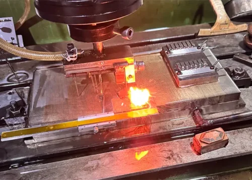

Electrical discharge machining (EDM) uses shaped electrodes and workpieces immersed in an insulating dielectric, such as kerosene. A pulsed power supply maintains a small discharge gap through automatic electrode feeding.
The discharge gap typically ranges from several micrometers to tens of micrometers. Pulsed sparks generate instantaneous temperatures exceeding 10,000°C, melting and vaporizing metal to reproduce the electrode geometry.
This process enables the machining of complex cavities and shaped holes. Deep-hole EDM refers to shaped-hole machining where the depth-to-discharge-gap ratio exceeds 50.
For example, a discharge gap of 0.1 mm corresponds to a deep-hole threshold exceeding 5 mm. Deep holes have extensive industrial applications, but their machining processes present significant challenges.
Deep blind-hole machining occupies most processing time, allowing eroded particles to accumulate within the discharge gap. Poor debris evacuation causes molten material to accumulate between the electrode and workpiece.
Some particles also adhere to the machined surface, weakening discharge performance and reducing machining efficiency. Surface deposits further complicate cleaning and affect processing quality.
Therefore, understanding the relationship between discharge gaps and debris evacuation channels is essential for improving deep-hole EDM. This study investigates electrode structures that transform deep-hole machining conditions into shallow-hole machining conditions.
The proposed approach aims to improve machining efficiency and economic performance through optimized electrode geometry and debris evacuation.
Analysis of the Deep-Hole Electrical Discharge Machining Process
Machining of Deep Shaped Holes in Typical Components
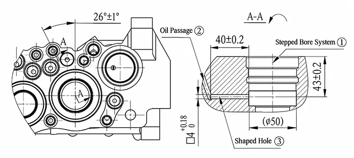
The research examines a complex cast aluminum alloy housing containing numerous internal cavities and interconnected holes. One deep-hole EDM operation connects an annular groove with an oil passage, as illustrated in Figure 1.
The shaped hole reaches a depth of 40 mm and requires approximately 759 minutes of machining. This lengthy processing time demonstrates the low efficiency of conventional deep-hole EDM.
Machining Parameters for Shaped Holes
EDM is a special manufacturing process requiring verified machining parameters. Electrode material, current, discharge gap, dielectric fluid, and voltage directly influence machining performance.
Metallographic and physicochemical testing confirmed that the original machining parameters met quality requirements. The process used pure copper electrodes, a 3.7 A current, and a 0.16 mm discharge gap.
Additional parameters included EDM oil as the dielectric, a high voltage of 270 V, and a shaped-hole depth of 40 mm.
Electrode Structure for Machining Typical Shaped Holes
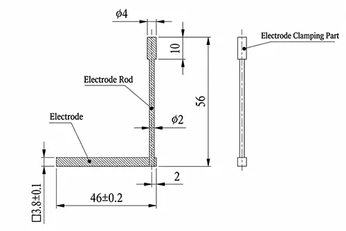
Conventional die-sinking EDM electrodes follow the geometry and dimensions of the required shaped hole. Their cross-sectional shapes generally match the hole profile, simplifying electrode design and manufacturing.
The original process used an integral square electrode with a side dimension of 3.8 mm. Figure 2 illustrates the electrode configuration used for the typical housing.
Analysis of the Machining Mechanism
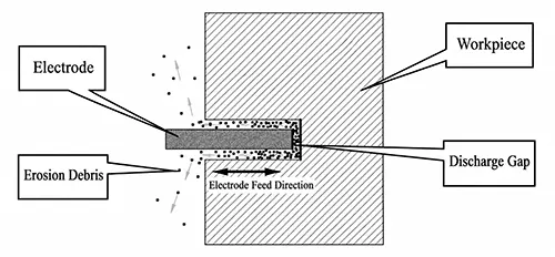
During EDM, electrode reciprocation helps dielectric fluid transport eroded particles through the gap between the electrode and workpiece. As hole depth increases, debris evacuation and heat dissipation become increasingly difficult.
Uneven electrode wear also develops, causing machining efficiency to decline sharply. Figure 3 illustrates the underlying deep-hole machining mechanism.
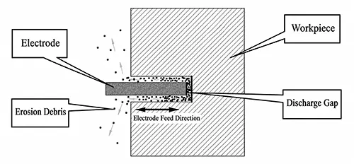
Debris evacuation presents a major challenge during deep-hole die-sinking EDM. Increasing hole depth makes molten erosion products difficult to remove from the discharge region.
Accumulated debris destabilizes electrical discharges and increases the likelihood of short circuits between the electrode and workpiece. These conditions interrupt machining and may damage both components.
Heat dissipation also significantly affects machining quality and electrode performance. High temperatures accumulate in deep discharge regions, increasing electrode wear and workpiece thermal deformation.
Excessive thermal exposure reduces dimensional accuracy and may alter the material properties of the workpiece. Uneven electrode wear creates another important machining challenge.
Electrical discharges erode both the workpiece and electrode, gradually changing electrode geometry. Complex discharge conditions produce uneven energy distribution and different wear rates across the electrode surface.
Consequently, electrode deformation makes dimensional and geometric accuracy difficult to maintain. Debris accumulation, insufficient cooling, and uneven wear interact, causing unstable machining quality.
Technical improvements are therefore necessary to meet modern manufacturing requirements for high-precision and high-efficiency deep-hole EDM.
Influence of Shaped-Hole Depth on Machining Efficiency
The study compared EDM processing times for aluminum alloy housings with identical materials and shaped-hole cross-sectional dimensions. Different machining depths provided data for evaluating the relationship between hole depth and processing time.
Table 1 presents the machining time statistics collected from the original manufacturing process.
| Housing | Operation No. | Hole Cross-Section (mm) | Hole Depth (mm) | Machining Time (min) |
|---|---|---|---|---|
| Housing 1 | 430 | 4 × 4 | 4.8 | 12.2 |
| 435 | 4 × 4 | 7.9 | 17.7 | |
| 440 | 4 × 4 | 40 | 758.9 | |
| 450 | 4 × 4 | 9.7 | 27.1 | |
| 460 | 4 × 4 | 4.5 | 11.1 | |
| 465 | 4 × 4 | 3.4 | 8.6 | |
| 470 | 4 × 4 | 5 | 13 | |
| 475 | 4 × 4 | 4.3 | 10.5 | |
| Housing 2 | 480 | 4 × 4 | 18.4 | 130.8 |
| 500 | 4 × 4 | 13 | 55.2 | |
| 565 | 4 × 4 | 28.6 | 353.8 | |
| 570 | 4 × 4 | 22 | 194.2 | |
| Housing 3 | 60 | 4 × 4 | 4 | 9.8 |
| 75 | 4 × 4 | 33 | 489.7 |
Table 1. Statistical Results of Electrical Discharge Machining Time
The original process used a 3.8 mm square electrode to machine shaped holes at different depths. Regression analysis established the following relationship between hole depth and machining time.
Machining Time (min) = 17.35 − 3.898D + 0.5179D2 + 0.001065D3
Here, D represents hole depth in millimeters. Figure 4 illustrates the fitted relationship between machining time and hole depth.
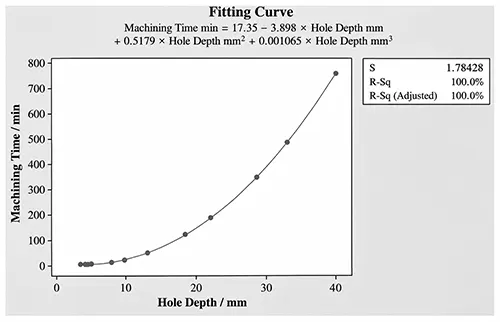
The results indicate that machining time increases as hole depth increases. Positive quadratic and cubic coefficients indicate an accelerating increase in processing time.
Influence of Shaped-Hole Depth on Machining Quality
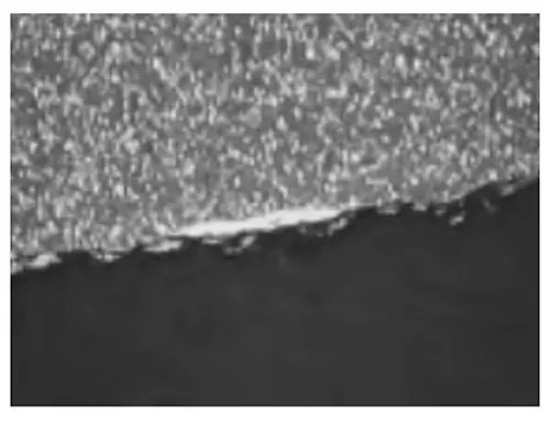
Metallographic examination revealed slight burning and black discoloration on surfaces machined at greater depths. Uneven surface features also appeared, indicating relatively poor machining quality.
Figure 5 presents the metallographic image of a deep shaped-hole machining specimen.
Design of an Improved Deep-Hole EDM Process
Deep blind-hole machining causes eroded particles to remain within the discharge gap, preventing efficient material removal. These particles weaken discharge performance and significantly reduce machining efficiency.
Changing the electrode structure provides a direct method for improving machining conditions. The proposed design enlarges the debris evacuation channel between the machined hole and rear electrode section.
Meanwhile, shortening the effective front electrode section creates machining conditions similar to shallow-hole EDM.
Preliminary Electrode Improvement Design
> Determination of Machining Requirements and Process Parameters
The original electrode material, current, discharge gap, dielectric fluid, and voltage followed equipment-recommended optimal settings. Special-process verification had already confirmed these parameters.
Therefore, the improved process retained the original machining settings to maintain product quality.
> Electrode Structure Design
The front electrode cross-section must mirror the required workpiece cavity geometry while allowing sufficient discharge clearance. This configuration maintains the intended shaped-hole profile during EDM.
According to the deep-hole definition, the effective front electrode length should remain below 5 mm. Uneven wear exceeding 0.5 mm generally requires electrode reconditioning before further machining.
Therefore, the front electrode length should range from 3 to 5 mm. This design improves machining efficiency while extending electrode service life.
The rear electrode section must provide a larger clearance than the normal discharge gap. Increasing this clearance creates a wider channel for debris evacuation.
However, the electrode must retain sufficient strength to prevent vibration during machining. Figure 6 illustrates the improved electrode mechanism.
Electrode reciprocation generates pushing and pulling forces that help remove erosion products from the machining region.
Preliminary Electrode Manufacturing Plan
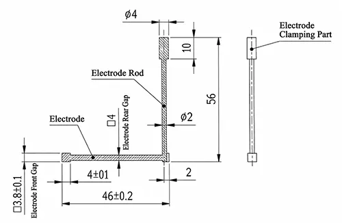
The preliminary design limits the front electrode length to less than 5 mm. The initial effective front section measures 4 mm to allow repeated reconditioning.
When uneven wear affects the machined profile, technicians can restore the electrode surface through trimming. The electrode is discarded once its effective front length falls below 1 mm.
This approach increases electrode utilization and extends service life. The rear electrode diameter remains smaller than the front section to provide adequate debris evacuation clearance.
Nine unilateral clearance values were selected for electrode manufacturing: 0.2, 0.3, 0.4, 0.5, 0.6, 0.7, 0.8, 0.9, and 1.0 mm.
Figure 7 presents the preliminary improved electrode design.
Electrode Experimental Plan
Tool-setting specimens were prepared for electrode trial machining. Each of the nine electrode configurations underwent testing under identical machining conditions.
Programs controlled machining depths at 5 mm intervals, covering 5 to 50 mm. The total processing time was recorded at each depth.
Experimental Data Analysis Plan
After trial machining, the researchers inspected surface appearance and dimensional accuracy. Regression analysis then evaluated machining time against hole depth and debris evacuation clearance.
The results helped determine suitable clearance requirements for efficient deep-hole EDM electrode design.
Implementation and Experimental Verification
Electrode Manufacturing and Workpiece Machining Tests
Electrodes were manufactured according to the preliminary improvement plan. Each electrode configuration underwent machining tests with programmed depth increments of 5 mm.
The maximum machining depth reached 50 mm. Cumulative machining time was calculated for each depth increment and electrode configuration.
Table 2 summarizes the experimental machining times for nine debris evacuation clearance values.
| No. | Depth (mm) | λ=0.2 | λ=0.3 | λ=0.4 | λ=0.5 | λ=0.6 | λ=0.7 | λ=0.8 | λ=0.9 | λ=1.0 |
|---|---|---|---|---|---|---|---|---|---|---|
| 1 | 5 | 12.4 | 10.8 | 10.2 | 10.1 | 10.1 | 10.1 | 10.0 | 10.1 | 10.0 |
| 2 | 10 | 26.5 | 23.6 | 21.3 | 20.4 | 20.5 | 20.4 | 20.2 | 20.1 | 20.2 |
| 3 | 15 | 52.9 | 38.9 | 34.7 | 31.2 | 31.3 | 30.9 | 30.5 | 30.3 | 30.0 |
| 4 | 20 | 91.4 | 58.6 | 49.8 | 42.9 | 42.8 | 42.4 | 41.7 | 41.5 | 40.6 |
| 5 | 25 | 151.6 | 98.2 | 71.4 | 55.3 | 55.0 | 54.5 | 53.6 | 53.0 | 52.7 |
| 6 | 30 | 239.1 | 155.7 | 105.5 | 69.8 | 69.5 | 69.2 | 68.4 | 67.5 | 66.2 |
| 7 | 35 | 348.8 | 243.2 | 148.2 | 86.5 | 85.0 | 84.3 | 83.2 | 81.8 | 80.5 |
| 8 | 40 | 516.4 | 385.5 | 212.4 | 114.6 | 105.7 | 103.6 | 101.5 | 98.2 | 96.6 |
| 9 | 45 | 722.2 | 534.5 | 307.1 | 148.7 | 137.5 | 134.0 | 130.1 | 123.8 | 118.3 |
| 10 | 50 | 1104.3 | 725.8 | 426.5 | 211.4 | 193.6 | 186.9 | 181.5 | 167.8 | 159.5 |
Table 2. Electrode Machining Test Time Statistics (Time: min; Clearance λ: mm)
Experimental Data Analysis
The researchers first compared machining times using electrode clearances of 0.2 mm and 1.0 mm. Figures 8 and 9 present the corresponding fitted curves.
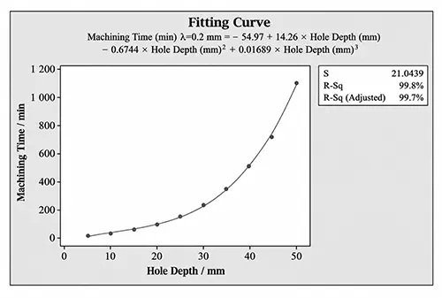
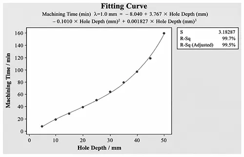
Both curves show accelerating increases in machining time as hole depth increases. However, larger debris evacuation clearances reduce the acceleration rate.
Polynomial regression established relationships between machining time, hole depth, and clearance. The following equations describe the experimental results, where D represents hole depth in millimeters and t represents machining time in minutes.
- λ = 0.2 mm: t = −54.97 + 14.26D − 0.6744D2 + 0.01689D3
- λ = 0.3 mm: t = 9.26 + 1.203D − 0.07222D2 + 0.006735D3
- λ = 0.4 mm: t = −12.84 + 5.287D − 0.2259D2 + 0.005912D3
- λ = 0.5 mm: t = −14.14 + 5.238D − 0.1879D2 + 0.003440D3
- λ = 0.6 mm: t = −14.08 + 5.147D − 0.1754D2 + 0.003081D3
- λ = 0.7 mm: t = −12.85 + 4.859D − 0.1598D2 + 0.002821D3
- λ = 0.8 mm: t = −12.18 + 4.683D − 0.1510D2 + 0.002666D3
- λ = 0.9 mm: t = −9.557 + 4.108D − 0.1191D2 + 0.002132D3
- λ = 1.0 mm: t = −8.040 + 3.767D − 0.1010D2 + 0.001827D3
The original electrode configuration produced the following regression relationship.
t = 17.35 − 3.898D + 0.5179D2 + 0.001065D3
Comparison of the regression equations reveals changes in the factors governing machining time. The analysis identifies linear and cubic depth terms as important indicators of processing time growth.
The linear term represents proportional growth, while the cubic term reflects accelerating growth. Figure 10 illustrates the relationship between the time acceleration indicator and debris evacuation clearance.
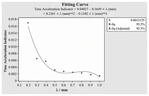
The fitted results indicate that increasing debris evacuation clearance reduces the acceleration of machining time growth.
Experimental Analysis Results
Machining time increased at an accelerating rate with increasing hole depth across all electrode configurations. However, larger debris evacuation clearances progressively reduced this acceleration.
When clearance exceeded 0.5 mm, machining times at identical depths tended to stabilize. Further clearance increases produced diminishing improvements in processing efficiency.
Therefore, the electrode should provide a unilateral debris evacuation clearance of at least 0.5 mm. This requirement must also account for electrode length, rigidity, and mechanical strength.
Maintaining sufficient structural stiffness while providing adequate clearance can significantly improve deep-hole EDM efficiency.
Practical Application
The experimental findings guided electrode optimization for batch machining of typical aluminum alloy housing components. The optimized design maintained sufficient electrode strength and rigidity while providing a clearance of at least 0.5 mm.
Machining parameters remained unchanged, including pure copper electrodes, a 3.7 A current, and a 0.16 mm discharge gap. EDM oil served as the dielectric, with a high voltage of 270 V and a hole depth of 40 mm.
The improved electrode featured a 4 mm front section to increase service life. Considering its slender geometry, the unilateral debris evacuation clearance was set to 0.5 mm.
Figure 11 illustrates the optimized electrode configuration for the typical component.
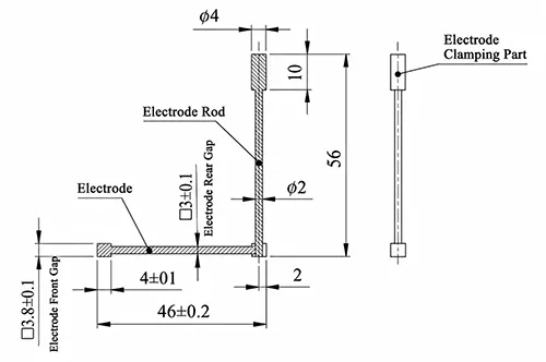
Batch production data showed that average machining time decreased from 756 minutes to 137.2 minutes. The study reported an approximately 4.5-fold improvement in machining efficiency.
Metallographic and physicochemical testing of the recast layer confirmed acceptable surface quality. Compared with the original process, the improved surfaces appeared smoother and more uniform.
No visible burning or black discoloration occurred after machining. Figure 12 presents the corresponding physicochemical examination report.
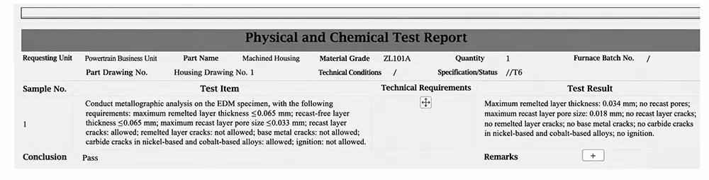
The improved workpiece surfaces showed no burning caused by inadequate debris evacuation or heat dissipation. Surface geometry remained stable without noticeable deformation from uneven electrode wear.
These results demonstrate that the optimized electrode effectively addresses debris removal, thermal management, and electrode wear problems in deep-hole EDM.
Conclusion
This study investigated electrode structure design and practical applications for deep shaped-hole EDM of aluminum alloy housings. The research established a systematic electrode design approach for improving deep-hole machining efficiency.
By shortening the effective front electrode section and enlarging rear debris evacuation clearance, the process creates conditions resembling shallow-hole machining. This structural improvement reduces debris accumulation and improves discharge stability.
Experimental analysis indicates that a clearance of at least 0.5 mm provides significant efficiency improvements while preserving electrode strength. Batch manufacturing verification demonstrated shorter machining times and improved surface quality.
The proposed electrode design addresses the limitations of conventional deep-hole die-sinking EDM. It offers a practical method for improving productivity and manufacturing economics in complex precision components.