
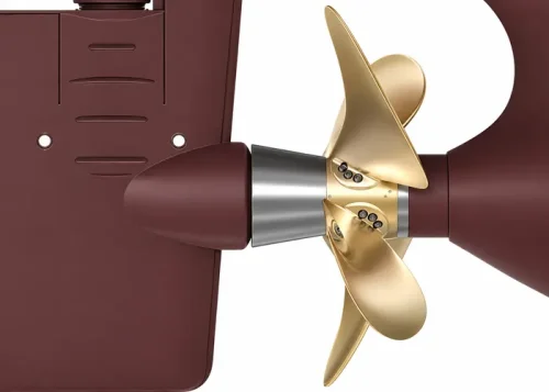

A marine propeller converts engine power into thrust, allowing a vessel to move forward or backward. During housing machining, elastic deformation can cause the cutting tool to deflect away from the workpiece.
Excessive boring bar overhang and insufficient dynamic stiffness can reduce machining accuracy. Researchers have investigated vibration-damping boring bars, error compensation strategies, and machining processes for difficult materials.
Passive dynamic vibration absorbers and actively controlled damping boring bars have achieved progress. However, specialized damping systems for large-span, thin-walled housings remain insufficiently studied.
Tool deflection and vibration can reduce bearing bore coaxiality, affecting marine propeller operating performance. Variable-support damping boring bars offer a potential solution for deep-hole machining and thin-walled components.
These systems incorporate an adjustable sliding support sleeve near the middle or rear section of the boring bar. A variable-damping medium between the sleeve and bar responds to real-time vibration conditions.
By adjusting damping characteristics during machining, the system improves stability and supports high-precision boring operations.
Design of High-Precision Boring Technology for Marine Propeller Housings
Variable-Support Damping Boring Bar for Suppressing Tool Deflection and Vibration
Deep-hole boring machines are used to machine marine propeller housings. Their main components include a worktable, spindle head, boring bar support, and workpiece support.
The boring bar and workpiece supports carry the machining system’s weight and part of the cutting load. A motor drives the spindle head, rotating the boring bar and cutting tool assembly.
The workpiece support uses an adjustable screw mechanism to accommodate different workpiece dimensions. Meanwhile, the boring bar support helps transmit cutting forces during machining.
Under typical boring forces, weak structural regions are identified. Sealed fixtures are then installed at corresponding locations outside the housing.
Residual stresses remain inside the housing after casting. Material removal during machining redistributes these stresses and can cause additional deformation.
Therefore, a variable-support damping boring bar is designed with an annular groove near its middle and rear sections. A support sleeve assembly is installed within this region.
The housing stiffness during operation of the variable-support damping boring bar is expressed as follows:

Here, Kdyn represents housing stiffness during operation, while K0 represents the static stiffness of an unsupported boring bar. The parameter cs denotes the damping coefficient, and ks represents contact stiffness between the support sleeve and housing.
The parameter m represents the equivalent boring bar mass, while η denotes the effective energy dissipation efficiency of magnetorheological fluid. The term τy(H) represents shear yield stress under magnetic field strength H.
Additionally, A represents the effective shear area of the damping layer, and δ represents boring bar bending deformation.
When Kdyn exceeds K0, the system exhibits greater stiffness. Increased shear yield stress allows the damping layer to convert mechanical vibration energy into heat.
Sliding contact and damping energy dissipation jointly suppress bending rebound under cutting forces. Consequently, the system reduces regenerative chatter during boring operations.
Progressive Coaxiality Error Compensation Using Laser Tool Setting and Dual-Head Boring
Removable reference bridge plates are installed outside the bearing bore locations at both ends of the housing. High-precision locating pinholes provide a unified coordinate reference for tool setting and measurement.
Left and right boring heads are installed at opposite ends of the CNC boring machine worktable. Both heads share a spindle drive system and rotate synchronously through a dual-output gearbox.
The key technical parameters are presented in the following table.
| System | Subsystem / Equipment | Parameter | Value / Specification | Remarks / Tolerance |
|---|---|---|---|---|
| Dual-Head Boring System | Left and Right Boring Heads and Drive System | Installation Position | Both Ends of CNC Boring Machine Worktable | Coaxial Opposing Arrangement |
| Drive Method | Shared Spindle Drive System | Dual-Output Gearbox | ||
| Rotational Speed Synchronization Accuracy | ±0.5% | Controls Synchronization Between Both Heads | ||
| Laser Tool Setting Instrument | Laser Transmitter and Receiver | Laser Beam Diameter | 5 mm | — |
| Measurement Accuracy | ±0.001 mm | Precision Measurement of Tool Tip Position | ||
| Components | Laser Transmitter, Receiver, Signal Processor | — | ||
| Installation and Positioning | Horizontal Angle Between Laser Beam and Spindle Axis | 90° | Determines Radial Tool Tip Position | |
| Laser Tool Setting Instrument | Installation and Positioning | Height Deviation Between Laser Beam Plane and Spindle Axis | ≤0.02 mm | Ensures Measurement Reference Alignment |
Table 1. Key Parameters for Boring Operations
Laser Tool Setting and Initial Coaxiality Measurement
During tool setting, the left or right boring tool rotates into the laser beam plane. The tool tip interrupts the beam and generates an optical blocking signal.
The instrument measures each tool tip’s coordinate difference relative to the reference bridge plate locating holes. These measurements support compensation for the initial coaxiality deviation between both boring tools.
The compensation relationship is expressed as follows:
Δt = Δ1 + Δ2 + Δ3
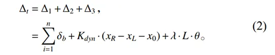
Here, Δt represents the initial coaxiality value after compensation. The parameters Δ1, Δ2, and Δ3 represent coarse alignment, laser tool setting, and long-guide-sleeve directional compensation.
The parameter δb represents the initial eccentricity of blank bore b. The coordinates xR and xL represent measured tool tip positions, while x0 represents theoretical alignment coordinates.
Additionally, λ denotes the guide sleeve directional correction coefficient, L represents sleeve length, and θ represents angular deviation between the boring bar and reference axes.
Three compensation stages are applied sequentially to establish progressive error correction conditions.
Optimized Layered Precision Boring with Residual Stress and Surface Integrity Control
Uneven material removal can cause residual stress deformation during marine propeller housing boring. Nickel-aluminum bronze also tends to develop hardened surface layers during machining.
To address these challenges, the process combines symmetrical spiral milling, natural aging, layered precision boring, and vibration-monitored adaptive feeding. A round-edge polycrystalline diamond boring tool supports coordinated control of residual stress and surface hardening.
A five-axis machining center generates a spiral milling toolpath around the housing reference axis. The spiral begins at the blank bore center and extends toward the inner wall.
Climb milling directs cutting forces toward the bore center. This strategy helps maintain more balanced cutting conditions.
Quantitative Model of Residual Stress Release
The quantitative relationship between stress release and surface hardening control is expressed as follows:

Here, σr(r) represents residual stress at depth r from the surface. The parameter σ0 denotes initial surface residual stress after rough machining.
The parameter Kj represents the stress influence coefficient of cutting layer j. The term apj represents its stress attenuation coefficient, while rj denotes bore radius after machining layer j.
The exponential term e−βtj describes the time-dependent stress release relationship.
Layered Precision Boring and Natural Aging
An initial bore is produced from the solid blank through symmetrical spiral milling. The symmetrical toolpath balances cutting forces and reduces uneven residual stress distribution.
After milling, the housing is removed and placed horizontally on a dedicated aging platform. Support points correspond to the bearing seat positions at both ends.
The support span matches the housing’s actual operating configuration. A unilateral finishing allowance of 1.5 mm is divided into three machining layers.
The first layer uses a cutting depth of 0.8 mm for rough finishing. The second layer removes 0.5 mm during semi-finishing, while the final layer removes 0.2 mm.
All three layers are machined sequentially using the same boring tool. Bore diameter and roundness are measured after each layer to guide subsequent cutting adjustments.
Residual stresses redistribute after each material removal stage, producing additional deformation. However, progressively smaller cutting depths allow stress release to converge.
By the final finishing stage, residual stress reaches a very low level. This improves the dimensional stability of the finished bearing bore.
Experimental Investigation
The experimental workpiece was a marine propeller housing manufactured from CuAl10Ni5Fe4 nickel-aluminum bronze. After casting and rough machining, the bearing bore region retained a unilateral machining allowance of 2.0 mm.
The experiment evaluated changes in housing residual stress and bearing bore coaxiality. These measurements assessed the effectiveness of the proposed high-precision boring technology.
Experimental Procedure
A TK6916 CNC floor-type milling and boring machine was used for the experiment. The machine featured a 58 kW spindle and a rotational speed range of 10–2000 rpm.
Additional equipment included a dual-output gearbox, dual-head boring system, laser tool setting instrument, and variable-support damping boring bar. Both boring heads provided radial micro-adjustment resolution of 0.001 mm.
The relevant machine parameters are listed below.
| Category | Parameter | Value |
|---|---|---|
| Worktable Parameters | Worktable Dimensions | 3000 × 8000 mm |
| Worktable Load Capacity | 60 t | |
| Maximum Workpiece Width | 3800 mm | |
| Distance from Spindle Face to Worktable | 0–2500 mm | |
| Distance Between Columns | 4100 mm | |
| Worktable T-Slot Width | 28 mm | |
| Ram Parameters | Spindle Taper (7:24) | ISO50 |
| Tool Holder Specification | BT50 | |
| Pull Stud Model | P50T-I (45°) | |
| Spindle Speed Range (Three-Stage Hydraulic Stepless Speed Control) | 6–2000 rpm | |
| Main Motor Power | 58 kW |
Table 2. Boring Machine Parameters
After machining, the housing was transferred to an inspection room. It remained in a controlled environment at 20 ± 1°C for 24 hours before final inspection.
The marine propeller flow velocity distribution was then analyzed, as illustrated in Figure 1.
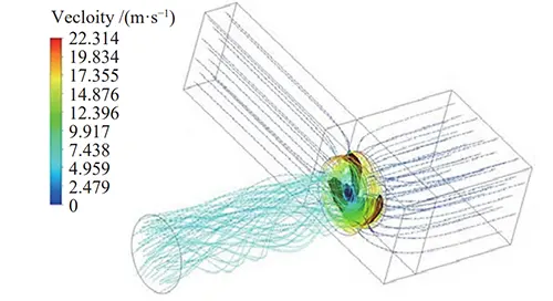
High-velocity regions exhibit greater flow speed and lower pressure. These areas are particularly sensitive to wall geometry errors and surface roughness.
Even small surface protrusions or depressions can cause cavitation, increased turbulence, and energy losses. Low-velocity regions are relatively less sensitive to localized geometric deviations.
Therefore, tolerance requirements can be relaxed appropriately in less critical regions. Machining resources should focus on areas with greater sensitivity to dimensional and surface errors.
Experimental Results
After rough machining, semi-finish boring, and finish boring, residual stress varied between −400 and 200 Pa. This range supported a favorable compressive stress condition and adequate housing machining stiffness.
The residual stress distribution of the marine propeller housing is illustrated in Figure 2.
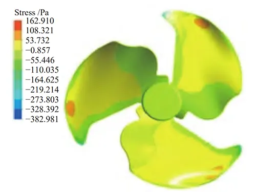
Measured housing stress ranged from −382.981 to 162.910 Pa. These values satisfied the residual stress requirements and indicated favorable machining stiffness.
Based on these results, bearing bore coaxiality was compared before and after machining optimization. The comparison is illustrated in Figure 3.
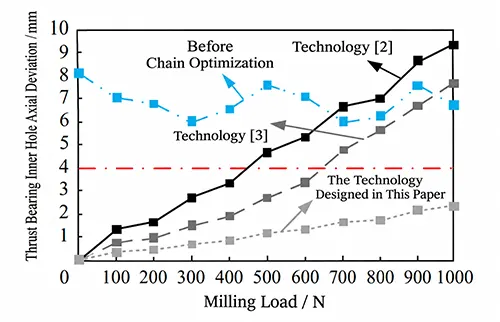
The variable support sleeve extends outward after entering the housing and contacts the previously machined bore wall. This converts the cantilever configuration into a simply supported or double-supported beam structure.
The improved support arrangement stabilizes the boring process and enhances machining quality. Experimental results show that bearing bore coaxiality reaches ≤4 μm under the proposed machining conditions.
Conclusion
The proposed high-precision boring technology improves marine propeller housing machining through vibration suppression, coaxiality compensation, and residual stress control.
For vibration suppression, low-melting-point alloy locally reinforces structurally weak housing regions. A variable-support damping boring bar further reduces tool deflection and machining vibration.
For coaxiality control, laser tool setting is integrated with dual-head boring. The process combines coarse alignment, real-time laser feedback, and long-guide-sleeve directional compensation.
These three compensation stages progressively reduce alignment errors. As a result, the maximum coaxiality error across five bearing bores remains within the required range.
For surface integrity and stress control, symmetrical spiral milling is combined with natural aging and layered precision boring. Round-edge polycrystalline diamond tools and vibration-monitored adaptive feeding further reduce surface residual stress.
Overall, the experimental results demonstrate improved machining stability and bearing bore accuracy. The proposed method provides a practical approach to high-precision manufacturing of marine propeller housings.