
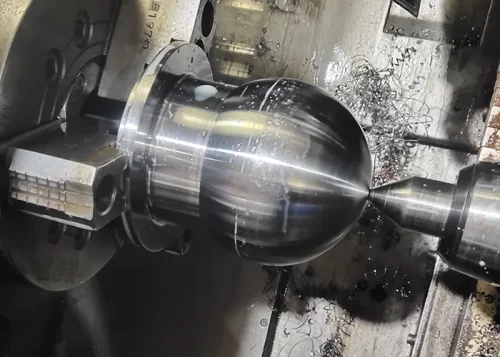





CNC technology has achieved rapid development in recent years. CNC machine tools have become the core processing equipment for mechanical manufacturing.
This trend puts forward higher requirements for the professional skills of CNC operators in the manufacturing sector.
Current CNC machine tool tool compensation parameter verification adopts two primary methods: manual verification and automatic verification.
Both methods have significant limitations and are susceptible to human error. In manual verification, workers manually input tool compensation parameters.
While this allows for manual verification of the parameters, it cannot completely eliminate issues such as incorrect input of tool edge position information and parameter values caused by human oversight;
Therefore, the risk of human error is relatively high. The automatic calibration method places high demands on the hardware and system of CNC machine tools.
Furthermore, it still requires manual inspection of issues such as tool clamping and tool wear, meaning it cannot completely eliminate human intervention.
Additionally, when operators load tools manually, mismatches between the actual tool and the program-called tool greatly raise the risk of tool collision.
In light of the shortcomings of existing verification methods, Shanghai Turbine Works has independently developed a new intelligent online verification system for CNC machining.
This paper presents the developed system in detail.
It elaborates on key functions including machine tool data entry, tool compensation parameter verification, and pre-machining tool inspection.
This study aims to provide a reliable reference for the design and implementation of automatic verification schemes for CNC machining tool compensation parameters.
Overview of the Calibration System
This paper presents a novel intelligent online calibration system for CNC machining.
The system adopts a three-tier working mechanism, including automatic data input, multidimensional parameter verification, and tool reliability evaluation.
It effectively avoids potential machining accidents. Moreover, the system ensures that tool parameters consistently match actual operating conditions.
Traditional tool parameters must be manually measured and entered into the machine tool, and human error can lead to issues such as incorrect tool compensation calculations and parameter input errors.
The system described in this paper improves upon standard tool setters by establishing a data flow of “parameter standardization—QR code storage—automatic entry,” thereby achieving automated data input from the tool setter.
Additionally, the machine tool data control method and supporting system described in this paper feature functions such as automated parameter setting, real-time data verification, and dynamic wear compensation.
Introduction to System Modules
Automated Input of Tool Setter Data
Advances in tool technology have led industrial production to gradually adopt high-precision tool setters.
For the online calibration system for CNC machining described in this paper, technicians achieved automated data acquisition through the following three key improvements:
1) Optimization of tool setter functionality. Technical improvements were made to standard tool setters to enhance the accuracy and stability of parameter measurements.
2) Standardization of parameter formats.
This study defines the output format specifications and standardizes the data structure for tool presetter parameters.
This prevents data reading errors caused by inconsistent formats.
3) Application of QR codes as information carriers.
This study encodes the standardized tool parameters into QR codes, prints the codes, and attaches them to the tool bodies.
After machine operators complete tool installation, they use a custom-designed barcode scanner to scan the QR codes, automatically entering the tool compensation parameters into the machine tool.
This technology completely replaces manual data entry, significantly improving data entry efficiency and accuracy.
Tool Compensation Parameter Verification System
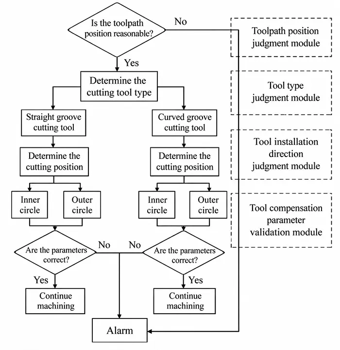
To fully eliminate machining quality issues stemming from manual tool setting and manual parameter entry, this study integrates a tool compensation parameter verification system into the proposed platform.
Its operational logic and core modules are shown in Figure 1.
1. Cutting Edge Position Detection Module
This module automatically judges whether the cutting edge sits in the correct position according to the actual clamping position of the cutting tool.
If an error is detected, the system immediately triggers an alarm, prompting the operator to make timely corrections.
2. Cutting Tool Type Identification Module
By identifying the positions of the first and second cutting edges, this module accurately identifies the cutting tool type, providing the basis for subsequent parameter verification.
3. Tool Mounting Direction Detection Module
Based on cutting edge position data, this module determines the tool’s current machining target and clarifies the machining position attributes.
The system establishes multi-scenario verification rules based on the analysis of dual-cutting-edge positions, simultaneously assessing the correctness of parameters and the reliability of the tool.
Its core process is as follows: (1) Cutting edge selection: For straight-groove cutters, the “lower cutting edge” is designated as the first cutting edge;
For curved-groove cutters, the “right cutting edge” is selected for internal circular machining, and the “left cutting edge” for external circular machining;
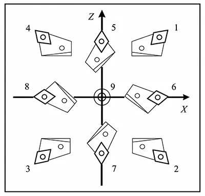
(2) Validity check: The positions of the nine cutting edges on the right tool holder of a vertical lathe are shown in Figure 2.
Using this as an example, a configuration is deemed valid only when the cutting edges are adjacent (e.g., “1 and 2”);
If the cutting edges are in the same or opposite positions (e.g., “1 and 1,” “1 and 3”), an alarm is triggered immediately.
4. Tool Compensation Parameter Verification Module
The tool compensation parameter verification module acquires core machining information.
The obtained data includes cutting edge direction, tool type, and real-time machining position.
Based on the above information, this module comprehensively verifies the tool compensation parameters input to the machine tool.
This includes checking whether the parameters correspond to the correct cutting edge position, whether the positive and negative signs are correct, and whether the tool holder configuration is reasonable.
Successful verification allows the machine tool to proceed with machining tasks, while failed verification triggers an immediate system alarm.
5. System Application Features
This system offers two key flexible application features: first, it can operate independently to meet the needs of a single machining scenario;
Second, it supports nesting and embeds into other cycle programs to adapt to complex machining processes.
Additionally, the system allows for the configuration of safety factors to ensure rationality.
For example, a safety factor can be set for X- or Z-axis parameter deviations caused by tool wear;
If these deviations exceed the specified range, an alarm is triggered.
Similarly, a safety factor can be set for X-axis parameter deviations resulting from incorrect tool holder installation;
If these deviations exceed the specified range, the system triggers an alarm.
The system also judges whether the tool processes the correct workpiece according to the cutting edge position and provides an alarm function.
Tool Data Validation
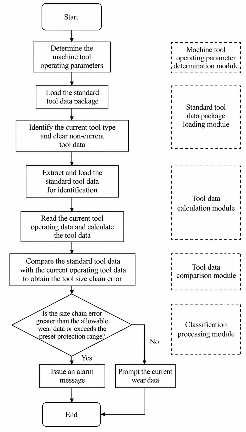
The machine tool data control method described in this paper establishes a standardized data processing workflow through five core modules, enabling automatic validation of tool data, as shown in Figure 3.
1. Machine Tool Parameter Verification Module
Before the machine tool begins operation, this module verifies and sets basic tool-related parameters, providing a standard basis for subsequent data validation.
The system uses data stored within the tool holder to distinguish between single-edge and double-edge tools (e.g., single-edge straight-groove cutters and double-edge curved-groove cutters), while also identifying the tool type (e.g., standard tools, square-shank tools).
2. Tool Standard Data Package Loading Module
The system loads the tool standard data package using standard data.
The tool data verification system automatically identifies the type of tool currently in use on the machine tool, then clears data related to tools not currently in use or sets the data for the currently active tool to
“0” by default, extracting and loading only the standard data for the current tool to prevent interference from irrelevant data.
For single-edge tools, the system retains only the data of the currently active tool.
For double-edge tools, it stores separate data for both cutting edges to avoid machining errors arising from edge confusion.
Meanwhile, the system sets the safety factor corresponding to different tool types and verifies the program tool (data from the tool’s standard data package) against the currently active tool.
If operational data exceeds the safety factor or the currently active tool data equals “0”, the system halts the CNC machine tool and sends an alarm signal.
This module effectively ensures that the program tool matches the tool currently in use.
3. Tool Data Calculation Module
After the machine tool enters the operating state, the module acquires real-time operational data of the current tool.
It automatically integrates multi-source operational data, including information of the machine tool, cutting inserts, and adapters.
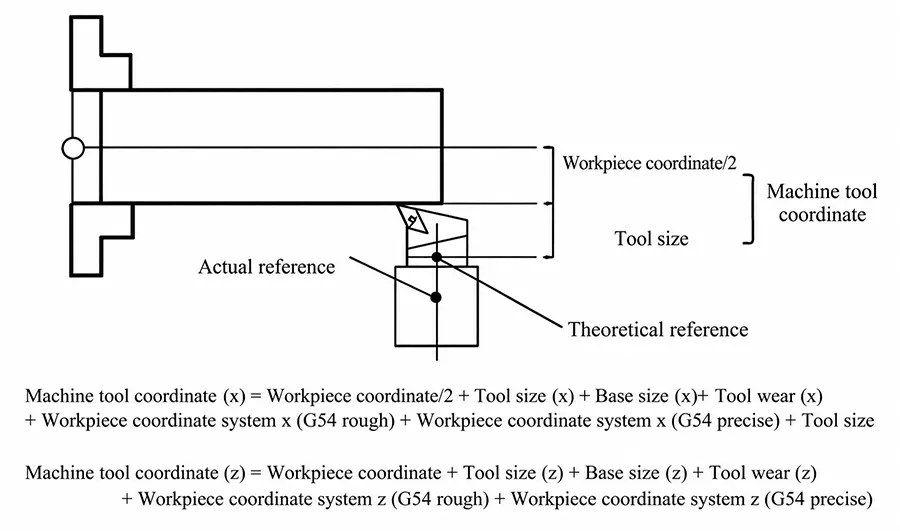
The system further integrates all collected data to construct a complete dimensional chain.
The tool moves from the zero position to the real-time working position during machining.
The module calculates the corresponding dimensional chain data throughout the tool movement process.
It acquires real-time motion data of the moving tool and compares it with standard reference data.
The system autonomously calculates dimensional chain error values from the comparative results.
Based on this, it automatically corrects the wear data for the X-axis or Z-axis.
The composition of the dimensional chain data is shown in Figure 4.
4. Tool Data Comparison Module
Factors including tool model, environment, and temperature generally affect errors in dimensional chain data.
This module compares the corrected wear data with the preset safety factor to determine whether the data falls within the safe operating range.
5. Classification and Handling Module
The module relies on the above comparison results as the fundamental basis.
It presents real-time error data on the human–machine operation interface.
The displayed data assists operators in evaluating tool life and the current machine tool operating status.
It also supports the classification and targeted disposal of various abnormal working conditions.
Safety limits vary for different machine tools and tool types.
This module adopts corresponding safety thresholds according to the equipment and tool categories.
It triggers alarms once the measured wear data exceeds preset safety limits.
The system notifies operators to carry out corrective actions.
This mechanism keeps the whole machining process under effective control.
System Performance Results
Implementing this online verification system yields the following outcomes:
Machining Quality
Before the system’s implementation, Shanghai Turbine Works experienced approximately 15 to 20 nonconformities per year caused by manual errors in tool parameter input.
Since the system went live, it has eliminated such nonconformities and resolved quality issues arising from tool compensation parameter errors.
Tool Life
Through precise wear monitoring and parameter correction, the system prevents excessive tool wear caused by parameter anomalies, extending tool life by 15–20%.
Manufacturing Costs
The system’s automated processing workflow simplifies operations for process technicians, significantly improves production efficiency, and reduces repair costs resulting from product nonconformities.
Each nonconformity requires approximately 20,000 yuan in labor and material costs to rectify;
The system saves 300,000 to 400,000 yuan annually in related repair costs.
Implementing this system reduces overall manufacturing costs by 8% to 12%, resulting in annual cost savings of approximately 2 million yuan.
Conclusion
This paper introduces an intelligent online verification system for CNC machining, comprising two core modules: tool compensation parameter verification and tool data validation.
The system enables automatic entry of tool parameters, multidimensional verification, and alerts for equipment anomalies.
It effectively prevents issues caused by human error during CNC machining and eliminates quality problems resulting from incorrect tool compensation parameters.
Practical application results validate the effectiveness of the proposed system.
The system eliminates machining nonconformities induced by human operational errors.
It significantly improves overall product quality and reduces comprehensive manufacturing costs.
Furthermore, it facilitates the transformation of traditional manufacturing toward informatization and intelligent upgrading.