





As core equipment for the precision forming of high-end components, the machining accuracy of CNC machine tools directly affects the consistency of component assembly and operational reliability.
Under the influence of loads, thermal conditions, and motion chain transmission, CNC machine tools are prone to issues such as positional and orientational drift of moving parts and deviations in tool paths.
Error sources exhibit characteristics of multi-path superposition and evolve depending on operating conditions;
The traditional approach of relying on manual, experience-based post-corrections often struggles to adapt to complex machining conditions.
This paper systematically analyzes the primary sources of machining accuracy errors in CNC machine tools.
Researchers analyze three key dimensions: structural characteristics, thermal deformation behavior, and motion chain performance.
Engineers propose corresponding error control technical solutions based on actual production conditions.
Major Sources of Machining Accuracy Errors
The process by which machining accuracy deviations arise in CNC machine tools exhibits distinct path characteristics.
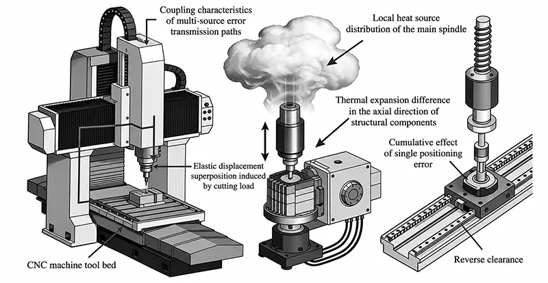
Structural, thermal, and motion pathways transmit various error sources to the tool-workpiece interface, where the errors mutually couple.
At the structural level, the bed, column, saddle, and spindle head collectively form the load-bearing path;
Stiffness differences of individual components and connection stiffness distribution exert influences on the machining system.
They lead to direction-dependent elastic displacement of the workpiece and cutting tool.
This phenomenon deteriorates the consistency of the motion trajectory.
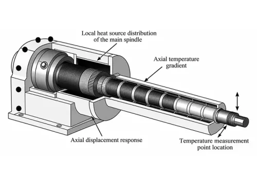
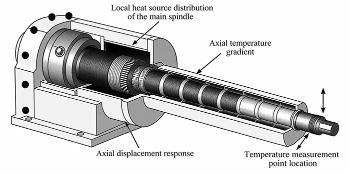
At the thermal behavior level, the operation of the spindle unit creates a localized heat source; heat is conducted along the spindle and adjacent components, forming a non-uniform temperature field.
Differences in thermal expansion among components accumulate over time, causing axial displacement of the spindle and drift in spatial geometric relationships.
At the motion chain level, pitch deviations and backlash exist in the ball screw and guide rail system;
Individual displacement deviations continuously accumulate during reciprocating motion, leading to a gradual deviation between the commanded trajectory and the actual trajectory.
The combined and coupled effects of the structural load-bearing path, thermal field evolution, and motion chain deviations during the machining process are shown in Figure 1.
Techniques for Controlling Machining Accuracy Errors in CNC Machine Tools
Suppressing Deviations Caused by Structural Stiffness Constraints in Machine Tools
1. Mechanism of elastic displacement deviation under variable cutting loads
CNC machine tools bear variable cutting loads during the machining process.
Each link in the load-bearing chain features inconsistent stiffness values.
This stiffness discrepancy results in uneven elastic deformation distribution across the structure.
The unbalanced deformation further induces relative positional offsets between the cutting tool and the workpiece.
Such deviations show obvious directional dependence, and changing the feed direction significantly amplifies the asymmetric characteristics of the displacement response.
2. Dual-stiffness coordination principle and key influencing factors
Structural constraint design requires careful consideration of overall load-bearing stiffness and local connection stiffness.
Single local reinforcement may trigger internal load redistribution inside the structure.
Such load redistribution tends to amplify displacement responses in non-critical directions.
Dual-stiffness coordination effectively avoids this adverse effect and ensures structural stability.
In engineering practice, the continuity of the load path, the configuration of support spans, and the consistency of forces at connection interfaces directly influence the convergence level of elastic displacement.
3. Definition of comprehensive structural deviation index and structural optimization method
To characterize the level of elastic displacement deviation under structural stiffness constraints, a comprehensive structural deviation index D is introduced, calculated as follows:
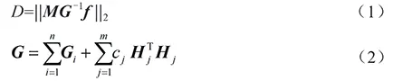
In the equation: D represents the comprehensive elastic displacement deviation index under structural stiffness constraints;
M is the directional weight matrix, used to reflect differences in displacement sensitivity across different feed directions;
G is the equivalent structural stiffness matrix of the entire machine;
f is the generalized cutting load vector; ||·||² is the L2 norm;
Gi is the stiffness contribution of the i-th structural sub-body; cj is the equivalent contact stiffness of the j-th connection interface;
Hj is the interface constraint mapping matrix.
In the structural optimization process, the convergence trend of index D is adopted as the core evaluation criterion.
Engineers coordinately adjust component cross-sectional parameters, support configurations, and connection preload distribution.
These optimizations effectively restrain the superposition of elastic displacements.
This strategy keeps the structural posture deviations within a stable range.
Identification and Compensation of Thermal Deformation Evolution Characteristics
1. Generation Mechanism of Spindle Axial Thermal Gradient
During CNC machine tool operation, local heat sources within the spindle unit generate heat that conducts along the spindle axis and toward adjacent components, thereby forming an axial temperature gradient.
Material parameters, structural dimensions, and heat dissipation conditions jointly affect the thermal behavior of the spindle system.
Different structural positions exhibit distinct temperature rise rates and thermal expansion degrees.
Such inconsistent thermal responses lead to spindle axial displacement.
They also induce deviations in the spatial geometric relationship of the overall structure.
2. Temporal Evolution Characteristics of Thermal Errors and Quantitative Mapping
Such deviations present obvious temporal characteristics and weakly correlate with variations in cutting conditions; single measurement fails to reflect their evolutionary process.
Figure 2 illustrates the formation of axial temperature gradients under conditions of localized heat source distribution within the spindle and the effects of differences in axial thermal expansion among components.
This paper mainly conducts thermal deformation identification based on spindle axial displacement.
It establishes a quantitative mapping relationship between temperature state variations and pose deviations.
The proposed method realizes the decoupling of thermal deformation errors from other error components, including structural errors and motion chain errors.
This study provides a reliable foundation for the precise identification and compensation of thermal errors.
3. Construction and Engineering Application of Thermal Deformation Response Index
To describe the effect of thermal behavior on axial displacement deviation, the thermal deformation response index T is introduced, which is calculated as follows:

In the equation: T is the axial displacement response index caused by thermal deformation;
R is the displacement mapping weight matrix, used to reflect differences in the sensitivity of different measurement points to axial displacement; S is the equivalent thermal flexibility matrix;
θ is the temperature state vector, composed of temperature measurement points on the main shaft and adjacent components;
Sk is the flexibility contribution of the kth thermal response element;
∆τk is the temperature change over the corresponding time interval.
Continuously tracking the thermal deformation evolution process via this metric allows researchers to isolate and compensate for axial thermal expansion and contraction effects, thereby maintaining geometric drift within a controllable range.
Regulation and Correction of Cumulative Motion Chain Errors
The motion chain of a CNC machine tool consists of a servo drive, ball screw, guideway pairs, and connecting components.
Geometric deviations and transmission backlash exhibit a gradual accumulation during reciprocating motion.
Non-uniform screw pitch causes displacement increments to vary with stroke length;
Deviations in guideway straightness result in deviations from the intended motion direction;
And reverse backlash creates transient mismatches during direction changes.
The combined effect of these factors results in a continuously expanding deviation between the commanded displacement and the actual displacement.
This type of error shows distinct path-dependent characteristics, and motion direction, stroke segment, and direction-change frequency strongly influence it;
A single calibration is insufficient to suppress its long-term effects.
To describe the accumulation of motion chain errors over the stroke, the displacement accumulation error index E is introduced, calculated as follows:

In the equation: E represents the cumulative error index of the motion chain; q represents the number of discrete segments within the stroke;
Al represents the segment direction mapping matrix, used to characterize the amplification effect of error accumulation in different motion directions;
∆xl represents the deviation vector between the commanded displacement ul and the actual displacement vl in the lth motion segment;
bl is the segment offset term introduced by backlash and transmission slack.
This metric enables researchers to identify the error distribution characteristics of different travel segments.
Engineers implement differentiated control strategies for direction-change segments and long-travel segments.
This approach restrains the growth rate of displacement deviation and keeps motion accuracy stable.
Engineering Application Validation
Experimental Design
This study aims to verify the applicability of multiple precision control methods for CNC machining.
These methods include structural stiffness constraints, thermal deformation identification and compensation, and motion chain error control.
The study selects a typical vertical CNC machine tool as the experimental verification subject.
Researchers keep the workpiece, tool type, and machining path consistent, and establish baseline and optimized operating condition groups for comparative testing.
The baseline operating condition group retained the machine tool’s original structural parameters and control strategies to reflect the natural superposition of multi-source errors.
The optimized operating group adopted multiple improvement strategies.
These measures include structural stiffness constraints, spindle thermal state identification parameters, and segmented motion chain control methods.
This study further investigated variations in the system operating state under different error suppression strategies.
Test metrics included structural pose deviation, spindle axial displacement, displacement within the motion chain’s travel range, and machining dimensional deviations.
These metrics correspond to structural, thermal, and motion chain error characteristics, respectively, and reflect the impact of different control elements on the stability of machining accuracy.
Results and Analysis
Test data related to machining accuracy under different test conditions are shown in Table 1.
In terms of structural pose deviation, the maximum pose deviation at the tool tip in the reference condition group reached 12.37 μm, with a standard deviation of 4.91 μm;
Structural stiffness constraints were introduced into the optimization scheme.
The corresponding evaluation values of the optimized condition group decreased to 6.82 μm and 2.36 μm, respectively.
Meanwhile, the optimized strategy substantially reduces the amplitude of pose fluctuation.
These improvements prove that adjusting the load-bearing path effectively enhances overall structural stability.
Regarding spindle axial displacement, the peak value and fluctuation amplitude for the baseline operating conditions group were 9.74 μm and 3.28 μm, respectively;
The optimized group adopts thermal deformation identification and compensation strategies.
The maximum and mean displacement deviations dropped to 4.63 μm and 1.47 μm, respectively.
This outcome effectively restrains the cumulative axial thermal expansion trend over time.
This study further evaluated the displacement consistency of the motion chain.
The baseline operating conditions group exhibited a maximum stroke displacement deviation of 8.69 μm.
Its corresponding mean displacement deviation was 5.14 μm.
Researchers implemented a segmented control strategy for the motion chain.
After optimization, the corresponding evaluation metrics of the operating conditions group decreased to 3.92 μm and 2.41 μm, respectively.
In addition, the displacement distribution within the working stroke became more balanced and uniform.
The reference operating conditions group produced a mean machining dimensional deviation of 7.83 μm.
Its coefficient of variation for dimensional consistency reached 0.46.
In comparison, the optimized operating conditions group reduced the mean dimensional deviation to 3.58 μm and the variation coefficient to 0.21.
These results demonstrate improved machining dimensional stability.
Such improvements are achieved by the synergistic effect of multiple error control measures.
| Group | Tool Tip Maximum Pose Displacement (μm) | Pose Displacement Variance (μm) | Axial Displacement Peak Value (μm) | Axial Displacement Fluctuation Amplitude (μm) | Maximum In-Stroke Displacement Deviation (μm) | Mean Displacement Deviation (μm) | Mean Machining Dimensional Deviation (μm) | Dimensional Consistency Dispersion Coefficient |
|---|---|---|---|---|---|---|---|---|
| Baseline Condition Group | 12.37 | 4.91 | 9.74 | 3.28 | 8.69 | 5.14 | 7.83 | 0.46 |
| Optimized Condition Group | 6.82 | 2.36 | 4.63 | 1.47 | 3.92 | 2.41 | 3.58 | 0.21 |
Table 1. Test Results of Machining-Accuracy-Related Indicators Under Different Test Conditions
Conclusion
This paper systematically analyzes the sources of machining accuracy errors in CNC machine tools from the perspectives of structure, thermal deformation, and motion chains, and proposes targeted error control solutions.
Engineering application results demonstrate that through comprehensive global error control, structural position and orientation deviations, spindle axial displacement, and motion chain displacement deviations have all been effectively suppressed, resulting in improved dimensional stability during machining.
This research provides a feasible technical approach for controlling the machining accuracy of CNC machine tools under complex operating conditions and holds significant engineering and reference value for enhancing the stability of the machining process and ensuring the quality of high-end component batch production.