





High-precision CNC machine tools serve as the core foundation of high-end equipment manufacturing, and their performance directly impacts the quality and efficiency of precision parts machining.
The spindle housing serves as a core functional component of machine tools.
Its geometric accuracy, dynamic and static stiffness, as well as thermal stability are key performance indicators.
These properties directly determine the overall machining accuracy and operational reliability of the entire machine tool.
Modern manufacturing fields including aerospace and precision mold production continuously raise higher standards for machining accuracy and efficiency.
Driven by such industrial demands, spindle housing components are evolving toward ultra-high precision, enhanced structural rigidity and improved thermal stability.
However, spindle housings feature intricate structures and uneven wall thicknesses.
Their hole systems also impose extremely stringent precision requirements.
During actual machining, multiple adverse factors jointly affect these components.
These factors cover cutting force, cutting heat, fixture deformation and inherent geometric errors of machine tools.
Such coupled interference leads to various prevalent machining problems.
Severe machining vibrations and uncontrollable thermal deformation frequently occur.
Dispersed machining procedures also generate continuous cumulative errors.
These defects greatly restrict the further improvement of the overall machining accuracy and production efficiency of spindle housings.
To solve the above practical machining bottlenecks, this research selects the cast iron spindle housing of a vertical machining center as the research object.
It proposes an innovative integrated process optimization method.
This method integrates structural manufacturability optimization, cutting parameter optimization and customized fixture design.
Furthermore, it combines the multi-source error integrated compensation technology consisting of online detection, model prediction and real-time compensation.
We ultimately establish a collaborative optimization system integrating process improvement and error control.
Through systematic technical innovation, this study effectively resolves core machining problems of spindle housings.
These key problems include insufficient structural rigidity, excessive thermal deformation, obvious machining vibration and cumulative machining errors.
The research outcomes provide a feasible and comprehensive technical scheme.
It supports the high-efficiency, stable and high-precision batch machining of precision spindle housing components.
Optimization Design of Spindle Housing Machining Processes
In the field of precision manufacturing, the machining accuracy of high-precision CNC machine tool spindle housings directly determines the overall performance of the machine tool.
Currently, traditional machining processes face various limitations that make it difficult to meet the ever-increasing demand for high precision.
Multiple restrictive factors hinder the high-quality machining of spindle housings.
These limitations mainly involve machining vibration, uneven tool wear, thermal deformation, and inherent geometric errors of machine tools.
The coupling of these adverse factors makes it difficult to achieve ideal machining accuracy and qualified surface quality for spindle housing components.
Therefore, the optimization of CNC machine tool spindle housing machining processes has become a crucial technical approach.
It helps improve the comprehensive performance of machine tools and satisfies the increasingly stringent high-precision machining demands in modern manufacturing.
To achieve high-precision, high-efficiency machining of spindle housings, we address key issues including structural rigidity, thermal stability, and machining vibration.
This study focuses on the cast-iron spindle housing of a specific model of vertical machining center, which has external dimensions of 1,200 mm × 800 mm × 600 mm.
The precision requirements for the spindle mounting hole are IT5 grade, with coaxiality ≤ 0.008 mm and end-face runout ≤ 0.010 mm.
The optimized structural design of the spindle housing is shown in Figure 1.
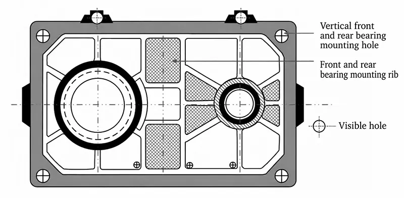
Figure 1 shows the structure of the spindle housing, which we design to meet requirements for structural rigidity and thermal stability.
To solve the problems of the original fragmented manufacturing process consisting of rough milling, semi-finish boring, and finish boring, we implement comprehensive process optimization.
First, we optimize structural manufacturability by adding process-oriented ribs to non-critical areas inside the housing and standardizing the wall thickness to (20±1) mm, which enhances the rigidity of the casting and reduces residual stress.
We design the front and rear spindle bearing bores as stepped through-holes to reduce overhang during deep-hole boring and enhance the rigidity of the machining system.
Following these optimizations, the housing’s mass increased by approximately 5%, and its natural frequency improved by approximately 18%.
Next, we optimize the cutting process parameters.
Considering the machinability characteristics of HT300 material, we adopt the orthogonal experimental design method to optimize finishing parameters.
A coated carbide boring tool was employed; with a fixed cutting depth of 0.2 mm, the optimized combination of finishing boring linear speed vc = 180 m/min and feed rate f = 0.08 mm/r was obtained. resulting in a surface roughness of Ra ≤ 0.8 μm and a reduction in radial cutting force fluctuations of approximately 30%.
Minimal lubrication was adopted in place of traditional flood cooling to reduce thermal shock.
At the same time, we redesign the fixture system and clamping scheme.
We develop a specialized hydraulic combination fixture to complete the finishing of critical hole patterns and flat surfaces on the housing in a single setup.
The fixture’s clamping force is uniformly adjustable (0.5–1.5 MPa).
This study conducts analysis and targeted optimization on the layout of component support points.
The optimization ensures that the maximum elastic deformation of the spindle housing during clamping stays within 5 μm.
This strategy guarantees consistent alignment among the machining reference, design reference and assembly reference.
It further eliminates systematic errors induced by reference misalignment during the machining process.
Design of a Multi-Source Error Integration and Compensation System
To mitigate thermal deformation, geometric errors, and force-induced deformation during machining, we develop an error compensation system centered on “online detection—model prediction—real-time compensation”.
We install eight temperature sensors near the spindle bore and key positions on the housing wall, and adopt the displacement sensor built into the spindle unit to monitor axial thermal expansion.
We establish a temperature rise–thermal displacement model based on multiple linear regression, as shown in Equation (1).

In the equation: ΔL is the axial thermal displacement compensation, in μm;
a0 is the initial offset constant, in μm; n is the total number of temperature sensors mounted on the housing; i is the sensor index;
ai is the regression coefficient corresponding to the i-th temperature sensor, in μm/°C;
Ti is the real-time measured temperature value of the i-th temperature sensor during the machining process, in °C;
Ti,0 is the reference temperature value of the i-th temperature sensor in the initial steady-state condition of the system (e.g., after startup and warm-up), in °C.
This study uses a laser interferometer to detect and compensate for machine tool geometric errors.
To address positional errors in the housing hole pattern, we employ a spatial error model to realize segmented compensation for XY-plane positioning errors through the pitch compensation function of the CNC system.
Furthermore, we indirectly evaluate cutting forces by monitoring the spindle load current and adaptively adjust the feed rate once the load exceeds the threshold to reduce force-induced deformation.
Experimental Validation and Effect Analysis of Process Optimization
This study constructs a three-level testing framework to fully verify the effectiveness of the proposed process optimization and error compensation strategies.
The testing system covers three progressive evaluation stages, including single-part trial cutting, small-batch machining validation, and final machine tool installation performance evaluation.
The study compared key precision metrics of the housing before and after process optimization and error compensation, as shown in Table 1.
| Key Accuracy Indicator | Coaxiality of Main Spindle Hole / mm | Flatness of Main Spindle Mounting End Face / mm | Position of Spindle Bearing Hole System / mm | Axial Thermal Displacement of Main Spindle Hole / μm | Surface Roughness of Precision-Bored Hole, Ra / μm | Vibration Amplitude During Machining / (m/s²) | Radial Runout of Main Spindle After Assembly / μm | Process Concentration / Processing Time / h |
|---|---|---|---|---|---|---|---|---|
| Before Optimization (A) | 0.012 | 0.015 | 0.025 | At a temperature rise of 20 °C: 15 | 1.6 | Dominant frequency during precision machining (~475 Hz), amplitude 2.0 | Before optimization, no direct dependency on part accuracy, typically > 3 | Multiple processes dispersed, multiple setups; total processing time per housing approximately 12 |
| After Optimization (B) | 0.005 | 0.008 | 0.010 | At a temperature rise of 20 °C: ≤ 3 | 0.8 | Dominant frequency during precision machining (~475 Hz), amplitude 1.2 | ≤ 2 | Key hole system and plane completed in one setup; total processing time per housing approximately 8 |
Table 1. Comparison of Key Accuracy Indicators Before and After Process Optimization and Error Compensation
As shown in Table 1, following process optimization and error compensation, the key accuracy metrics of the spindle housing have significantly improved.
The proposed optimization method achieves significant improvements in key machining accuracy indicators.
We optimize the coaxiality of the spindle bore from 0.012 mm to 0.005 mm, enhance the end face flatness from 0.015 mm to 0.008 mm, and improve the positional accuracy of the bearing bore system from 0.025 mm to 0.010 mm.
These prominent enhancements effectively guarantee the assembly precision and structural stability of the spindle housing.
When the temperature rises by 20 °C, axial thermal displacement is controlled within 3 μm (down from 15 μm), thereby mitigating the effects of thermal deformation.
The surface roughness (Ra) of the precision-bored surface was reduced from 1.6 μm to 0.8 μm, and the vibration amplitude at the natural frequency was lowered from 2.0 m/s² to 1.2 m/s², significantly improving surface quality and machining stability.
After assembly, the spindle’s radial runout is ≤2 μm, exceeding common industry standards.
The process achieves key features in a single setup, reducing the machining time per part from 12 h to 8 h, thereby significantly improving production efficiency and cost-effectiveness.
The study analyzed the machining consistency of the optimized housing spindle bore concentricity and the vibration signal spectrum, as shown in Figure 2.
As shown in Figure 2-1, for the five housings prototyped after optimization, the measured values of spindle bore concentricity stabilized between 0.004 and 0.006 mm, exceeding the design specifications (≤0.008 mm), with a process capability index (CPK) of ≥1.67.
This indicates that the process optimization and error compensation strategies improved machining accuracy, ensured consistency and stability in mass production, and demonstrated sufficient process capability.
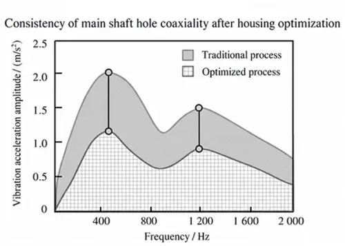
As shown in Figure 2-2, following process optimization, the amplitude of the dominant vibration frequency (approximately 475 Hz) during the fine boring stage decreased from 2.0 m/s² before optimization to 1.2 m/s², representing a 40% reduction.
These results indicate that structural rigidity enhancement and cutting parameter optimization can effectively suppress machining system vibration.
This provides a solid foundation for obtaining high-quality bore wall surfaces with the surface roughness controlled within Ra ≤ 0.8 μm and improving overall machining stability.
The experimental findings further verify that the combination of process optimization and multi-source error integrated compensation technology can significantly enhance the comprehensive machining performance.
It effectively improves the machining quality and production efficiency of high-precision CNC machine tool spindle housings.
Conclusion
This study addressed accuracy and stability issues arising from rigidity, thermal deformation, vibration, and multi-source errors during the machining of cast iron spindle housings for high-precision CNC machine tools.
Through integrated structural and process optimization (ribs, uniform wall thickness, stepped bores), cutting parameter optimization (orthogonal experiments yielded vc = 180 m/min, f = 0.08 mm/r, with minimal lubrication), specialized fixture design, and “online inspection—model prediction—real-time compensation” error control technology, a systematic process and compensation scheme was developed.
The experimental results present comprehensive performance improvements after optimization.
The natural frequency of the spindle housing increases by approximately 18%.
We stabilize the surface roughness at Ra ≤ 0.8 μm and reduce the cutting force fluctuation amplitude by approximately 30%.
We limit the axial thermal displacement to within 3 μm under a temperature rise of 20°C.
In terms of geometric precision, we maintain the coaxiality at 0.005 mm and achieve an end face flatness of 0.008 mm.
Furthermore, we shorten the overall machining time by 33% and control the assembled radial runout below 2 μm.
The above indicators fully demonstrate that the proposed method achieves remarkable improvements in both machining precision and production efficiency.
The limitations of this study include the lack of verification regarding applicability to dissimilar materials and larger workpieces;
Future research could focus on expanding process adaptability, as well as the lightweight design and engineering implementation of the compensation system.