





As modern manufacturing evolves toward higher precision, industries such as aerospace, automotive manufacturing, and medical devices are placing increasingly stringent demands on part accuracy.
Five-axis CNC machining centers, as key equipment for the efficient and precise machining of complex parts, have machining accuracy that directly impacts product quality.
However, during the actual milling process, the coupled effects of multiple factors—such as cutting forces and vibrations—can easily lead to machining errors, limiting further improvements in part accuracy.
To address this issue, researchers have conducted a series of studies on error control. To achieve comprehensive suppression of milling errors, this paper establishes a dynamic milling model.
It systematically analyzes various error sources throughout the entire cutting process.
Based on the analytical results, we formulate a targeted compensation control strategy.
This strategy realizes effective regulation of milling errors for five-axis CNC machining centers.
It further enhances the overall machining accuracy of processed workpieces.
Design for Error Control in Milling Operations on a Five-Axis CNC Machining Center
Development of a Dynamic Milling Dynamics Model
The milling process of five-axis CNC machining centers is susceptible to multiple interfering factors.
These factors mainly include machine tool geometric errors, inherent tool characteristic variations and unreasonable cutting parameter settings.
These adverse conditions lead to deviations in the actual motion trajectory of cutting tools.
Consequently, undesired machining errors occur during the milling operation.
Therefore, to effectively control these errors, this study first constructs a dynamic milling dynamics model based on the cutting process.
Dynamic Milling Model
The instantaneous dynamic cutting depth is a key parameter during the milling process;
It is closely related to tool vibration, and its dynamic behavior is shown in Figure 1.
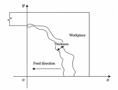
Based on its dynamic graphics and the milling process, we establish a linear cutting force model:

In the equation, Fij is the component of the tangential cutting force acting on the workpiece, Frj is the radial component of the cutting force acting on the workpiece, g is the rule for determining the milling cutter’s cutting state, t is the cutting time, αj is the milling cutter’s cutting angle, hj is the feed per tooth, δp is the axial cutting depth of the milling cutter, φt is the tangential cutting force parameter, and φr is the radial cutting force parameter.
Based on the above analysis results and the physical three-dimensional structure, we construct a dynamic milling model:

In the equation, F(t) represents the cutting force of the milling cutter;
N represents the number of cutting teeth involved in the cutting process; n represents the tooth number;
Ftn represents the tangential force of the nth tooth; Frn represents the radial force of the nth tooth;
And Fan represents the axial force of the nth tooth. Through the above process, a dynamic milling dynamics model is obtained.
By mapping this model to actual operating conditions, we realize real-time monitoring and provide a data foundation for subsequent error analysis.
Analysis of Cutting Errors
Based on the constructed model, we obtain the key parameters of the milling cutter during the cutting process and conduct simulations under ideal conditions via the simulation model.
By analyzing the differences between the two sets of data, we determine the x-direction deformation error of the cutting tool during the cutting process:

In this equation, ex represents the machining error caused by tool deformation in the x-direction, R0 is the cutting radius of the milling cutter, β is the normal-vector angle at the cutting point of the tool, and ζ is the quantification parameter for tool deformation.
At the same time, by considering the arc profile of the milling cutter along the cutting path, we determine the curvature radius and calculate the errors at the arc segment as follows:

In the equation, eθ represents the machining error at the arc segment, γ represents the central angle corresponding to the arc cut by the milling cutter, ρ0 represents the radius of curvature of the arc segment, Δx represents the change in the x-coordinate, and Δy represents the change in the y-coordinate.
Based on the above process, we determine the machining error of the milling cutter, providing a clear target for subsequent error control.
Implementation of a Strategy for Controlling Cutting Errors
Based on the above process, we determine the cutting errors.
Combined with the dynamic model established in this paper, we adjust the cutting force as follows:

In the equation, Fb represents the cutting force of the milling cutter in a five-axis machining center, CF is the cutting force coefficient, apx is the back depth of cut, fy is the feed rate, and vz is the cutting speed.
To prevent resonance between tool vibration and cutting force frequency, we calculate the natural frequency of the cutting process.
To keep the natural frequency sufficiently distant from the dominant frequency components of cutting force, we determine the cutting force operating frequency to realize effective machining error control:
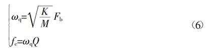
In this equation, ωq is the natural frequency of the cutting tool, M is the mass of the cutting tool, K is the stiffness of the cutting tool, and Q is the spindle speed.
Based on the above process, we achieve effective control of milling errors for the five-axis CNC machining center, thereby ensuring the dimensional accuracy of machined workpieces.
Experimental Analysis
Setting Up the Experimental Environment
This study monitors the cutting process of a milling cutter by constructing a dynamic milling dynamics model.
Based on the monitoring results, we analyze machining errors and implement compensation accordingly, realizing precise control of machining errors for five-axis CNC machining centers.
We conduct experimental verification to validate the effectiveness of the proposed method in cutting error suppression and machining accuracy improvement.
We select three five-axis CNC machining centers of the same model from a component manufacturing enterprise to establish the experimental platform.
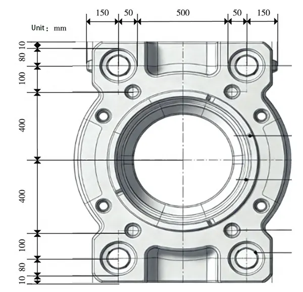
These machines are equipped with specified flat-end milling cutters for cutting experiments on aluminum alloy parts.
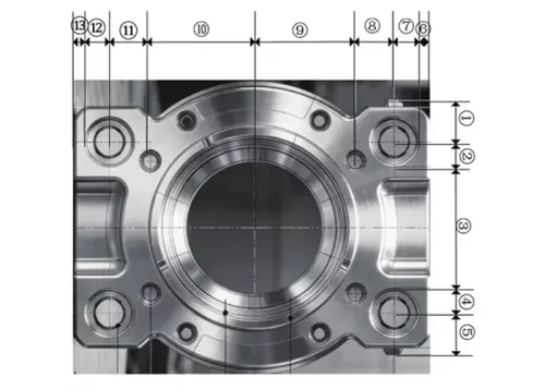
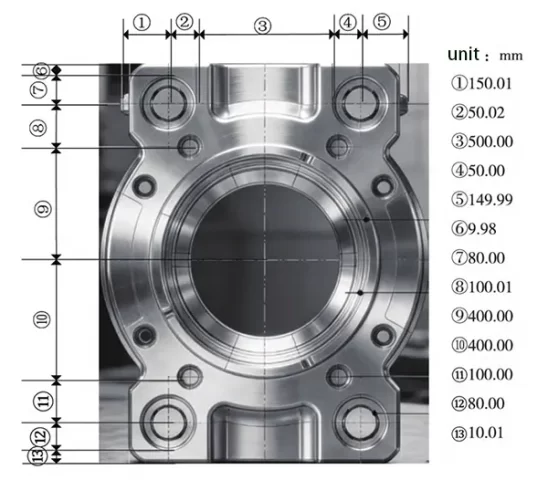
The machining drawings of the aluminum alloy parts are presented in Figure 2, and the relevant parameters of the adopted five-axis CNC machining centers are listed in Table 1.
| Machine Tool Table Size / mm | Maximum Turning Diameter / mm | Spindle Speed Range / (r·min⁻¹) | Rated Spindle Power / kW | Rated Spindle Torque / (N·m) | Cutting Feed Rate Range / (mm·min⁻¹) | Positioning Accuracy / mm | Servo Motor Control Accuracy / ° | Resolution / mm |
|---|---|---|---|---|---|---|---|---|
| 1200 × 800 | 1000 | 10–20,000 | 15 | 50 | 1–10,000 | ±0.005 | 0.001 | 0.001 |
Table 1. Five-Axis CNC Machining Center Parameters
Before the experiment, first mount the flat-end milling cutter on the spindle of the five-axis CNC machining center and perform dynamic balancing to ensure the stability of the cutting tool during high-speed rotation.
Next, install sensors at the designated positions to collect relevant parameter data.
At the same time, use Python 3.8 to code the methods described in the paper and develop the corresponding control platform.
Experimental Analysis of Milling Machining Error Control
To verify the effectiveness of the method described in this paper for controlling errors in milling operations performed by a five-axis CNC machining center, this experiment utilized the method to produce an aluminum alloy part.
We measure the dimensions at various positions on the part and obtain the experimental results presented in Figure 3.
Experimental verification demonstrates the superiority of the proposed method.
After implementing the optimized strategy, we control the dimensional deviations between machined parts and design specifications within ±0.001 mm.
This outcome proves that the presented method can effectively suppress machining errors in flat-end milling processes.
Analysis of Machining Accuracy Verification Results
We carry out this experiment to further verify the machining accuracy of parts processed by the improved method.
We collaboratively regulate the CNC machine tool through two core technical modules.
The first is a milling cutter flank wear error self-compensation method based on CMOS image sensor detection.
The second is a position envelope error optimization model for side milling cutters established via an improved immune clone selection algorithm.
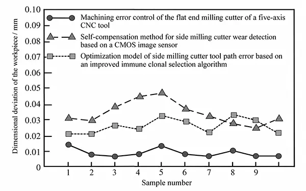
We calculate the overall dimensional deviation of the machined parts, and present the experimental results in Figure 4.
The experimental results reveal significant accuracy improvements under the proposed control method.
We control all overall dimensional deviations of machined parts within ±0.001 mm.
In comparison with the other two conventional methods adopted for contrast experiments, the developed method achieves substantially lower machining deviations, verifying its superior accuracy control performance.
This indicates that the method described in the paper can effectively improve the production accuracy of CNC machine tools.
Conclusion
Based on the dynamic milling model established in this paper, we monitor the part machining process and analyze cutting errors combined with the monitoring results.
Compensation and adjustments are made to address these errors, thereby achieving control over the milling accuracy of a five-axis CNC machining center and improving the dimensional accuracy of the produced parts.
Material property differences are not fully considered in this method. Such differences may increase cutting forces during machining.
Future research can perform adaptive analyses based on different material characteristics. This approach can further improve the control accuracy of the proposed method.