
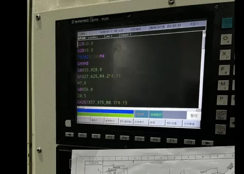





CNC lathes are widely-used core equipment in modern precision machining.
Safe standardised operation and competent programming capabilities are essential to prevent tool collisions, avoid equipment damage and produce qualified workpieces.
This article covers complete practical guidance for CNC lathe work:
It walks through pre-start-up inspections, auto-mode checklists, in-process emergency handling, shutdown procedures and routine equipment maintenance.
It further explains core programming knowledge including machine coordinate systems, tool-setting approaches, absolute-incremental programming modes, as well as commonly-used G-codes, M-codes and tool-radius compensation functions.
Combining theoretical explanations with practical examples, this material provides both novice learners and skilled operators with systematic reference for daily CNC lathe operation and programming.
Golden Rules for Operating CNC Lathes: Safety First, Follow the Procedures
When operating a CNC lathe, adhering to the standard procedures for the entire process—from startup to operation to shutdown—is the foundation for preventing tool collisions and ensuring safety.
Operators should not overlook any step:
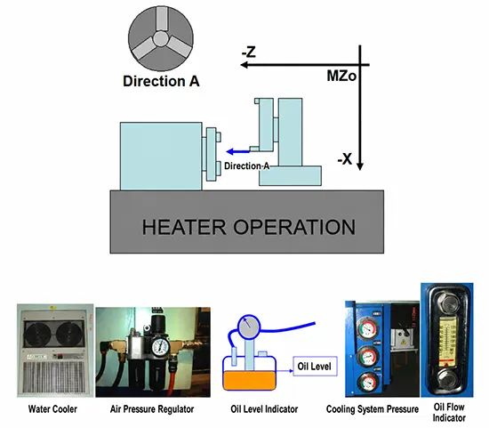
Essential Pre-Operation Checks: 6 Steps to Eliminate Potential Hazards
Immediately after startup, perform a home position return to calibrate the machine tool’s reference.
Check the pressure on the hydraulic gauge to ensure it meets the standard.
Inspect the lubrication system to ensure it operates smoothly without any jamming or abnormalities.
Verify that the oil and water levels are within the normal range.
Adjust the tool position to prevent clamping misalignment.
Test that the chuck extends and retracts smoothly without any sticking.
Rotate the spindle at a low speed of 300 rpm and perform a 10% rapid warm-up for 5–10 minutes.
Before AUTO Operation: 5-Point Checklist to Prevent Errors
Operators should confirm that the called program matches the workpiece being machined and that no programming errors exist.
Verify that parameters such as machining speed and feed rate are safe and appropriate.
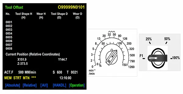
Verify the tool offset values, paying close attention to decimal points and positive/negative signs.
Disengage the mechanical interlock switch to prevent the machine from locking up.
Set the G00/G01 speed knob to 100% to ensure smooth operation.
In Operation & Shutdown: Emergency Procedures + Proper Closure
Emergency: Immediately press the emergency stop button; do not attempt to force the machine to continue operating.
Mid-process modifications: Double-check the starting position when adjusting tool compensation values or restarting the program.
Shutdown procedure: First press the emergency stop button → disconnect the power supply → clean the machine tool.
Daily precautions: Do not change speeds abruptly; when reversing direction, stop first before restarting.
Precautions for Operating CNC Lathes
1. Keep the control panel clean.
2. Clean the filter screen daily.
3. Avoid sudden speed changes; when reversing direction, stop the machine first before restarting it.
4. When shutting down the machine, press the emergency stop button first, then turn off the power.
5. Use approved lubricating oil and non-hazardous cutting fluid.
6. Avoid using air guns to clean the machine; use a vacuum cleaner or a brush instead.
7. Immediately repair and address any oil, water, or air leaks from the machine.
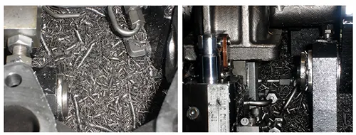
Example 1: Failure to clean the equipment after a shift:
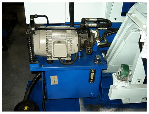
Example 2: The equipment is well-maintained and clean—a good example to follow:
Equipment Maintenance
Check the oil levels in all oil-using equipment daily; address any abnormalities promptly and top up as needed.
At the end of each shift, clean the machine tool thoroughly and apply rust-preventive oil to parts that require protection.
Monitor oil temperatures and color changes at all times to detect any machine malfunctions.
Periodically inspect all fasteners—such as screws, connectors, sockets, switches, and limit switches—for looseness.
Every three month, six month, and one year cycle, technicians adjust the machine tool’s level.
Based on actual operating conditions, all lubricating oils require scheduled replacement.
For open loop and semi closed loop equipment, lead screw clearance receives routine correction.
To guarantee processing performance, machine tool accuracy undergoes regular calibration and adjustment.
Inspection activities and problem solving outcomes demand detailed documentation for experience accumulation.
Core Programming Fundamentals: Coordinate Systems + Commands—Understand These, and You Can Program
The core of CNC programming lies in precisely defining coordinates and proficiently using commands. Once you master these, basic programming becomes a breeze!
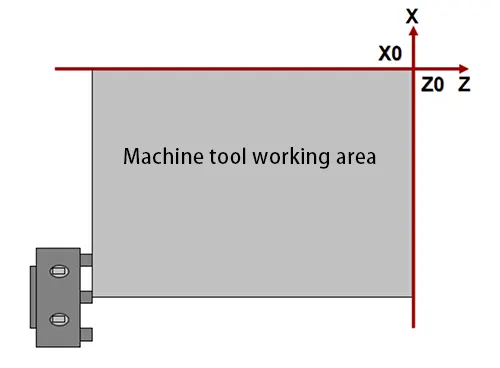
Machine Tool Coordinate System: Distinguish Between the X and Z Axes in a Second
Z-axis: Parallel to the spindle centerline; positive direction = away from the workpiece / dimensions increase.
X-axis: Perpendicular to the Z-axis; diameter command mode (programmed value = actual movement × 2).
Machine origin: A safety reference point set by the manufacturer; automatically resets to zero after power-on and homing; all movements are based on this point.
1. Tool Setting Techniques
(1)Test cutting method
The test cutting method is the most commonly used tool setting method in practice.
After operators clamp the workpiece and tool in place, they rotate the spindle and move the tool holder toward the workpiece to perform a test cut on a section of the outer circumference.
Then, while keeping the X-coordinate constant, move the Z-axis to raise the tool away from the workpiece and measure the diameter of that section of the outer circumference.
Enter this value into the “Tool Length” field of the corresponding tool parameters.
The system automatically calculates the position of the X-origin in the workpiece coordinate system by subtracting the diameter of the test-cut outer circle from the current X-coordinate.
Next, move the tool to perform a test cut on one end face of the workpiece.
Enter “Z0” in the “Tool Width” field of the corresponding tool parameters.
The system automatically subtracts the value just entered from the tool’s current Z-coordinate to determine the Z-origin of the workpiece coordinate system.
For example, if tool No. 2, mounted at X = 150.0, produces a cylindrical diameter of 25.0, then the program origin X-value for machining with this tool is 150.0 – 25.0 = 125.0;
If the end face is machined to 0 when the tool holder is at Z = 180.0, then the program origin Z value when machining with this tool is 180.0 – 0 = 180.0.
Enter (125.0, 180.0) into the X and Z fields of the “Tool Length” parameter for Tool No. 2, and use T0202 in the program to successfully establish the workpiece coordinate system.
In fact, finding the workpiece origin in the machine coordinate system does not involve determining the actual position of that point, but rather locating the tool holder’s position when the tool tip reaches (0, 0).
When using this method for tool setting, standard tools are generally not used; all tools to be used must be properly set before machining begins.
Common methods for setting the workpiece zero point on Fanuc CNC lathes.
2. Perform Tool Setting by Test Cutting Directly with the Tool
Use an external cylindrical turning tool to make a test cut on an external circle. Note the current X coordinate.
After measuring the diameter of the external circle, subtract the diameter from the X coordinate, and enter the resulting value into the X field under “Geometry” in the Offset dialog box.
Use an external cylindrical turning tool to make a test cut on the end face of the external circle.
Note the current Z coordinate and enter it into the Z field under “Geometry” in the Offset dialog box.
Basic Knowledge of Programming
Diameter-Based Command Method: Since workpieces machined on lathes are generally circular, drawings and measurements of inner and outer diameters are primarily based on diameter.
Therefore, the coordinate values for the X-axis of a CNC lathe are also specified using the diameter method. The actual movement of the cutting tool is only half the specified value.
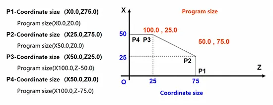
Programming Modes: Flexible Switching Between Absolute and Incremental
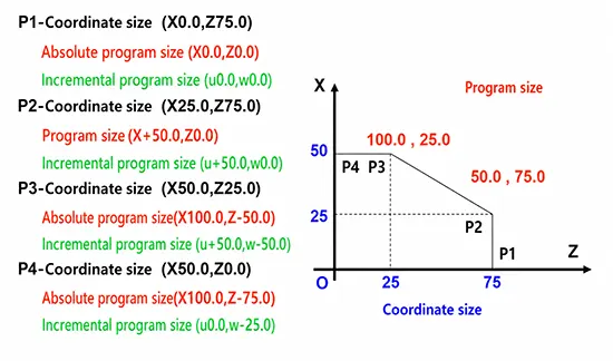
Absolute Programming (X/Z): Coordinates are fixed relative to the machine tool origin.
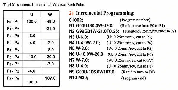
Incremental Programming (U/W): The previous position serves as the reference point; U = X increment, W = Z increment.
Advantage: Both modes can be used in combination, making them suitable for programming complex paths.
Complete Guide to Core Commands: M/S/F/T/G Codes—Master Them All in One Article
The “code” of CNC programming lies in the various commands.
By categorizing them for memorization and applying them clearly, you can double your programming efficiency.
Basic Functions (M Functions—Auxiliary Functions)
M functions are generally referred to as auxiliary functions.
They are denoted by the address word “M” followed by a two-digit number ranging from 00 to 99, with each number having a fixed meaning.
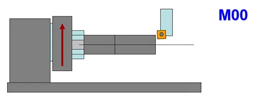
00: Program Stop
The program automatically runs until it reaches the M00 command (spindle stops, coolant shuts off, and program execution stops).
Press the “CYCLE START” button again to resume execution of the subsequent commands.
For example: When turning a part over for machining, reposition and re-clamp the part during the M00 interval, then continue machining.
(This method is generally not used in high-volume production because operator errors could result in scrap parts or machine damage.)
| Command | Function | Application Scenario |
|---|---|---|
| M00 | Program Stop | Workpiece dropped; fixture adjustment |
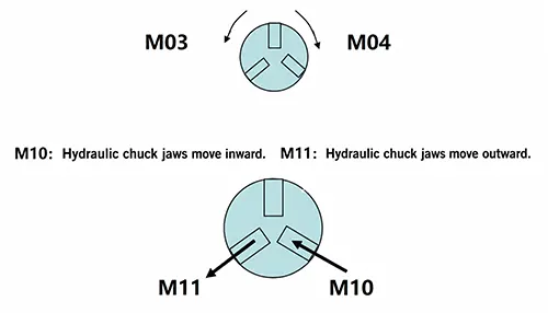
| M03 / M04 | Spindle Forward / Reverse Rotation | Start cutting operation |
| M05 | Spindle Stop | Tool change; before reversing spindle rotation |
| M08 / M09 | Coolant On / Off | Cooling during machining; chip removal |
| M30 | Program End and Reset | Machining completed; return to program start |
| M98 | Call Subprogram | Simplify programming of repetitive toolpaths |
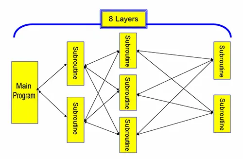
M98 calls a subprogram; M99 returns to the main program.
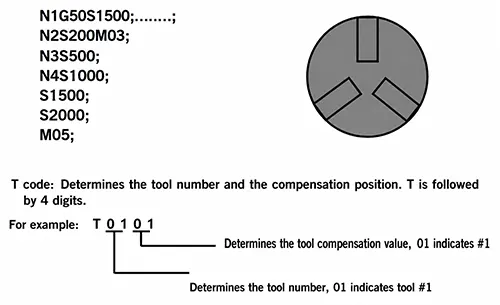
S/F/T Functions: Spindle Speed + Feed Rate + Tool
1. S Function: Spindle Speed
G97 Sxxxx: Fixed spindle speed (e.g., G97 S1000 = 1000 rpm)
G96 Sxxx: Constant linear speed (automatically adjusts spindle speed based on diameter)
G50 Sxxxx: Maximum spindle speed limit (to prevent equipment damage from overspeed)
2. F Function: Feed Rate
G99 Fxx: Feed per revolution (mm/r; e.g., F0.3 = 0.3 mm per revolution)
G98 Fxx: Feed per minute (mm/min)
3. T Function
Tool + Offset (4-digit number: first 2 digits for tool number + last 2 digits for offset number)
Example: T0101 = Tool No. 1 + Offset No. 1; T0212 = Tool No. 2 + Offset No. 12
For example: G50 S1500; this sets the maximum spindle speed to 1500 rpm.
Under this limit, the G96 function is restricted to a maximum spindle speed of 1500 rpm.
G-Code: Motion Path Control
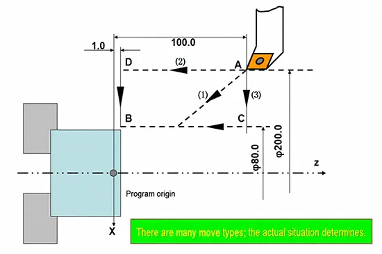
1. G00—Rapid Positioning
Moves the tool from its current position to the next command point at rapid feed rates along all axes.
The purpose is to reduce the time required for tool movement during non-cutting operations.
Command format: G00 X (U)——Z (W)——-;
2. G01—Linear Cutting
In this case, the tool moves in a straight line from its current position to the next command point at the feed rate specified by the F command.
Command format: G01 X (U)——Z (W)——F——;
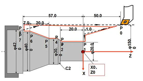
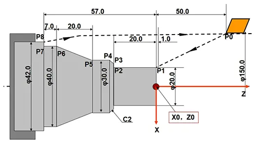
Machining Path: The tool moves from P0—then through P1, P2, …, to P8, and then returns to P0. See the table for the coordinates of each point.

The tool’s motion path is programmed using the absolute method.
G02/G03 Arc Cutting
This command causes the tool to perform an arc cutting motion within the specified X–Z plane.
Command Format:
G02 X (U)—-Z (W)—-R (I–K–) F—-; (clockwise rotation)
G03 X (U)—-Z (W)—-R (I–K–) F—-; (clockwise rotation)
Notes:
1) X (U) and Z (W) in the command represent the coordinates of the arc’s endpoint.
2) R is the radius of the arc; in this case, the arc angle must not exceed 180 degrees.
3) I and K represent the component vectors of the vector pointing from the arc’s starting point to the center on the X-axis and Z-axis, respectively.
This can represent any arc; pay special attention to the positive and negative signs when programming.
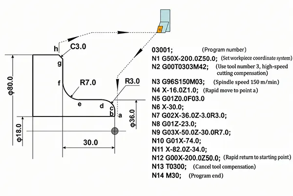
G02/G03 Arc Cutting Example:
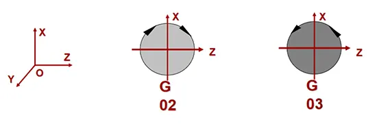
Examples of circular arc cutting in G02/G03:
Notes:
1) When programming, if the value of I or K is zero, it may be omitted.
2) Using the R parameter is much more convenient than using I and K, but it is limited to arcs less than 180 degrees.
For arcs greater than 180 degrees, you must use the I and K parameters or prefix R with a negative sign.
3) If a program contains I, K, and R, the R parameter takes precedence.
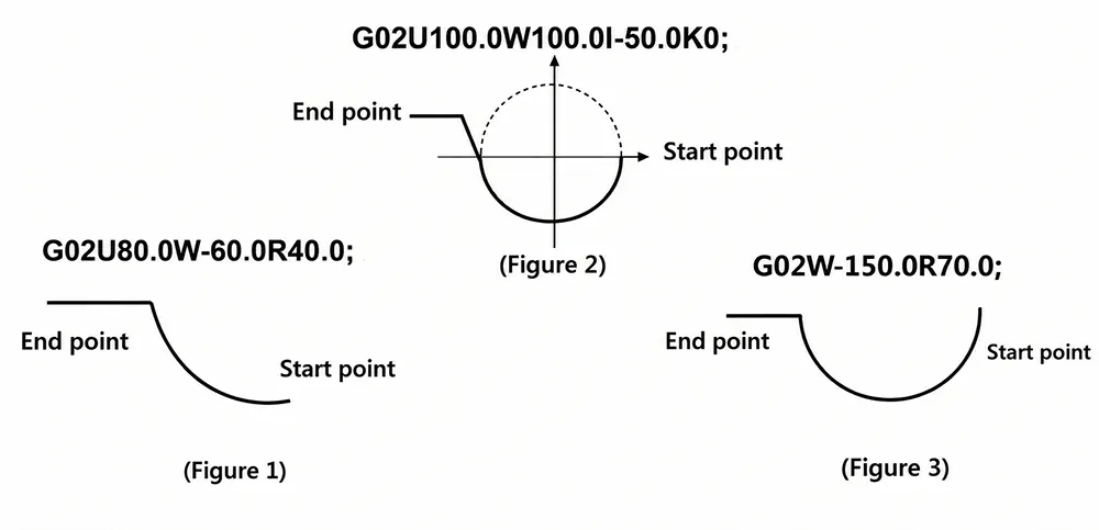
4) If neither I, K, nor R is specified, the system executes in G01 mode. (See Figure 1)
5) If an X, Z, U, or W value is omitted in a G02/G03 statement, the system controls a full-circle motion.
For example, G02 I 50.0; instructs the system to machine a circle with a radius of 50 mm and return to the starting point. (Figure 2)
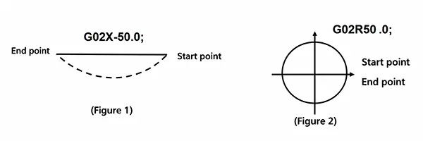
6) If the end-point coordinates are not on an arc:
(1) When either axis reaches the end-point coordinates, execute a linear movement along the other axis. (Figure 1)
(2) If neither axis can reach the end-point, execute a G01 command to reach the end-point when crossing quadrants. (Figure 2)
(3) If the specified R value is less than half the distance from the starting point to the end-point, the system executes a 180-degree arc and then proceeds.
G04 Pause
When this command is executed, all machine movements stop for the duration specified by the G04 command.
The program then continues with the commands in the next block. The G04 command is a single-byte command.
Command format: G04 X(U)—; or G04 P—; no decimal point is allowed after P.
Command Range: The minimum unit is 0.001 seconds, and the maximum command value is 999.999 seconds.
For example: When machining a groove, to achieve the required surface finish at the bottom of the groove, the tool pauses for an appropriate amount of time upon reaching the bottom.
This allows the workpiece to rotate more than one full revolution, removing any rough surfaces before retracting the tool.
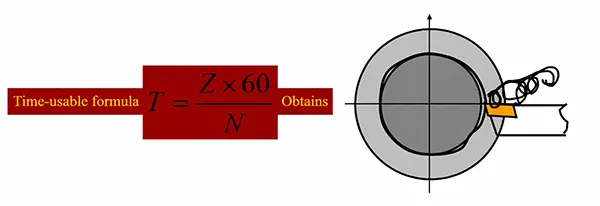
Assuming the spindle speed is 600 revolutions per minute, this equates to 600/10 = 10 revolutions per second.
If you want the tool to pause at the bottom of the groove to allow the spindle to rotate 2 revolutions before retracting, then 2/10 = 0.2 seconds.
The program is:
G04X0.2; or G04X200; G04U0.2;
or G04U200; G04P200;
P does not accept decimal points.
To be continue…