
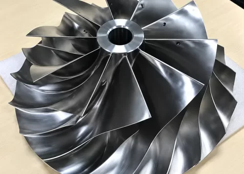





Manufacturers fabricate integral impellers as typical aerodynamic components that combine blades and hubs into a single unit.
They offer advantages such as light weight and the ability to avoid airflow losses caused by tenon joints, and are extremely common in the automotive, marine, and aerospace industries.
The machining of integral impellers involves efficient machining processes, CNC programming techniques for efficient machining, the selection and application of cutting tools for efficient machining, and intelligent control of the machining process; however, the machining process is extremely challenging.
The machining strategies differ depending on whether the impeller blades follow a streamlined direction or feature narrow flow channels.
Wang Zhongquan addressed the machining challenges of submersible pump impellers—including curved surfaces, narrow flow channels, and thin walls—by using multi-objective optimization to determine cutting parameters.
Combining UGNX and VERICUT virtual simulation, he resolved issues related to improving the precision and machining efficiency of thin-walled parts.
He Dong and colleagues optimized the machining paths and tool geometry for blades with narrow, twisted flow channel structures, thereby improving dimensional accuracy and surface quality. E. Artetxe et al. utilized a CAM solid modeler to perform multiple side milling operations, demonstrating significant accuracy in predicting geometric errors;
Users can integrate this method into composite machining programs to predict the machining deformation of impeller blades.
Furthermore, researchers have optimized machining strategies for impellers from various perspectives—including post-processing, simulation verification, and machining strategies—and achieved ideal results;
However, researchers have not yet thoroughly studied a comprehensive machining optimization scheme for integral impellers with diverter blades.
This paper focuses on an open, monolithic impeller with diverter vanes.
Using QJCAM CNC programming and VERICUT simulation technology, the authors optimized the design of the machining blank, cutting tools, machining paths, and post-processing.
Machining Plan Design
Centrifugal Impeller Structure
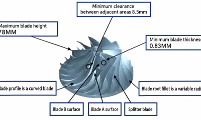
Designers configure centrifugal impeller blades as thin plates with large twist angles to improve the impeller’s aerodynamic performance.
The narrowest point between the blades and the deflector blades is only 8.5 mm, which limits tool accessibility, makes tool entry difficult, and makes interference highly likely.
The minimum thickness of the blades and deflector blades is less than 1 mm;
The blades are thin and long, resulting in unstable rigidity and a high risk of deformation during machining.
Designers connect the suction and pressure surfaces of the blades to the hub surface using transition fillets.
The fillet radii vary: the fillet radius on Surface A changes from 3 mm at the leading edge to 5 mm at the trailing edge, while the fillet radius on Surface B changes from 3 mm at the leading edge to 15 mm at the trailing edge, allowing for a smooth transition between the blades and the hub. See Figure 1.
Raw Part and Fixture Optimization
Manufacturers typically produce impeller blanks by forging. After forging the material into a bar, they turn it to create a rough-machined blank.
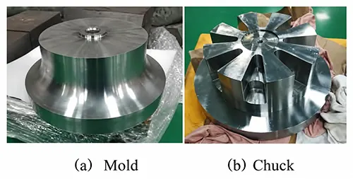
Operators use the blank’s upper surface as the rough reference surface and finish the lower bottom surface to act as the fine reference surface for other planes and hole patterns, as shown in Figure 2(a).
For five-axis simultaneous machining, the blank is fully positioned using a “one face, two pins” positioning scheme: the bottom face restricts 3 degrees of freedom, the center axis restricts
2 degrees of freedom, and the pins restrict 1 degree of freedom, thereby achieving complete positioning of the blank.
The fixture body has a bottom diameter of 300 mm. Engineers select conventional nut clamping. Figure 2(b) shows the actual fixture.
Cutting Tools and Parameter Design
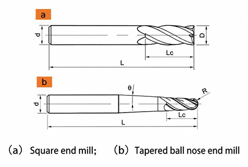
Machining is performed using a tapered ball-end mill, as shown in Figure 3(b), to balance rigidity and accessibility.
Open areas are rough-machined quickly using a large-diameter end mill, as shown in Figure 3(a).
The selection of spindle speed is related to both the initial cutting speed and the tool diameter.
When using a carbide tool, the cutting speed can be set to 30–90 m/min based on reference data, with a feed per tooth of 0.1 mm/r for rough machining, 0.05 mm/r for semi-finishing, and 0.03 mm/r for finishing.
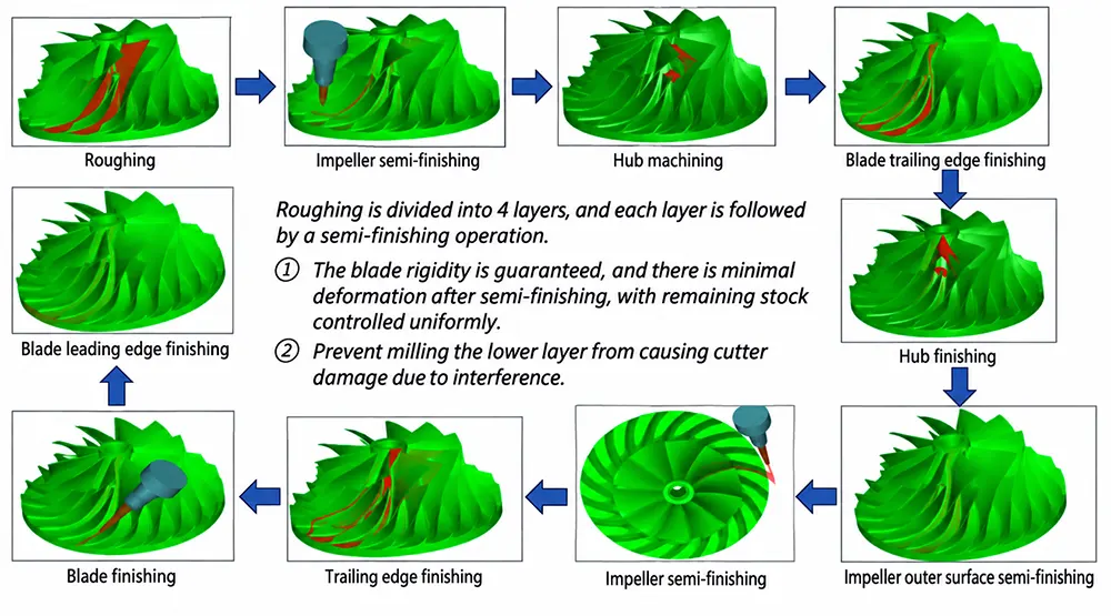
QJCAM software was used to optimize the programming of roughing, semi-finishing, and finishing toolpaths for an open, monolithic impeller with flow-diverting vanes;
Researchers used UG software for post-processing and verified the efficiency-enhancement scheme via simulation on a VERICUT machine. Figure 4 shows the toolpaths.
Simulation Results and Analysis
Rough Machining
Rough machining primarily targets the roughing of narrow flow channel areas, with the goal of rapidly removing material.
The cycloidal milling strategy is primarily used for rough machining.
Cycloidal milling is used to avoid fully submerged milling methods, such as slot milling, while fully satisfying the radial cutting depth requirements.
This reduces tool wear and extends tool life. The cycloidal milling strategy employs axial cutting depth to increase material removal rates.
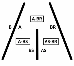
Researchers split the main vane into two surfaces, A and B, and separate the diverter vane into two surfaces, AS and BS, as shown in Figure 5.
1. Zoned Machining Scheme for Impeller Flow Channel Roughing
To avoid problems such as tool interference and full-depth cutting, operators can divide machining into zones:
The A-BR zone (upper part of the flow channel) is open and allows for easy tool entry;
The A-BS zone (lower-left part of the flow channel) has limited space, particularly at the junction with the A-BR zone, making it the most difficult area to access with the tool;
The AS-BR zone (lower-right part of the flow channel) is similar to the A-BS zone.
Machine the A-BR zone first, followed by the A-BS zone, and finally the AS-BR zone.
Introduce an appropriate rake angle during programming to prevent interference between the tool shank and unmachined material.
Use layered cutting to ensure cutting performance and tool life; determine the cutting layer depth based on the tool’s diameter and mass.
Given the cutting efficiency of cycloidal milling and the cutting capacity of Xiamen Jinlu tools, a cutting depth within 2.5 times the tool diameter is safe.
During the roughing process, as the milling cutter gradually approaches the blade root, the clearance between the main blades and the diverter blades gradually decreases, which is not conducive to tool shaft oscillation.
At this point, designers should reduce the ball head diameter of the tapered ball-end mill.
2. Layered Cutting Strategy and Process Parameters for Layer 1
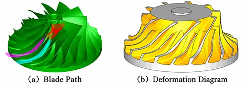
For this impeller, engineers divide the entire flow channel into 4 cutting layers, with a cutting depth of 20 mm per layer. The first layer features relatively open space;
A 12-mm end mill is used for rough machining over a large area, with a cutting width of 1 mm, a spindle speed of 3,500 r/min, and a cutting range covering 0% to 28% of the total flow channel depth.
The remaining parameters are shown in Table 1, and the machining results are shown in Figure 6.
| Parameter | A-BR Zone | A-BS Zone | AS-BR Zone |
|---|---|---|---|
| Feed rate / (mm·min⁻¹) | 3000 | 2500 | 2500 |
| Feed amount / (mm·r⁻¹) | 0.17 | 0.14 | 0.14 |
| Cutting depth / mm | 22 | 20 | 20 |
Table 1. First Rough Machining Layer
3. Machining Process for Layers 2 to 4 with Gradually Miniaturized Tools
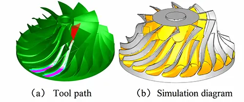
For the second layer, engineers selected cycloidal milling and high-feed spot milling.
The tools chosen were a 12-mm end mill and an 8-mm tapered ball-nose end mill.
The spindle speed remained constant; see Table 2 for the remaining parameters, and Figure 7 for the results.
| Parameter | A-BR Zone | A-BS+AS-BR Zone | A-BS+AS-BR Zone | A-BS+AS-BR Zone |
|---|---|---|---|---|
| Feed Speed (mm·min⁻¹) | 3000 | 1500 | 2700 | 3000 |
| Feed per Tooth (mm·r⁻¹) | 0.21 | 0.10 | 0.19 | 0.21 |
| Cutting Depth (mm) | 20 | 10 | 10 | 20 |
| Cutting Width (mm) | 1 | 0.38 | 0.8 | 1 |
Table 2. Second Layer of Rough Machining
For the third layer, engineers also selected cycloidal milling and high-feed spot milling.
An 8-mm tapered ball-nose end mill was chosen, with parameters as shown in Table 3; the results are shown in Figure 8.
| Parameter | A-BR Zone | A-BS + AS-BR Zone | A-BS + AS-BR Zone |
|---|---|---|---|
| Feed rate / (mm·min⁻¹) | 1800 | 1500 | 2000 |
| Feed amount / (mm·r⁻¹) | 0.128 | 0.107 | 0.143 |
| Cutting depth / mm | 22 | 20 | 1 |
| Cutting width / mm | 0.8 | 0.38 | 0.4 |
Table 3. Parameters for the Third Rough Machining Layer
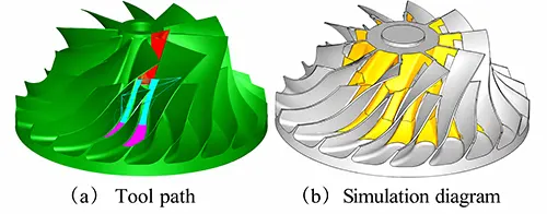
The fourth layer was machined using a 6-mm tapered ball-end mill with high-feed spot milling, with the spindle speed remaining constant;
See Table 4 for the remaining parameters. The results are shown in Figure 9.
| Parameter | A-BR Zone | A-BS+AS-BR Zone | A-BS+AS-BR Zone | A-BS+AS-BR Zone |
|---|---|---|---|---|
| Feed Speed (mm·min⁻¹) | 1200 | 1800 | 1000 | 1500 |
| Feed per Tooth (mm·r⁻¹) | 0.1 | 0.14 | 0.0625 | 0.093 |
| Cutting Depth (mm) | 16 | 10 | 0.55 | 7.2 |
| Cutting Width (mm) | 0.35 | 0.3 | 0.5 | 0.3 |
Table 4. Parameters for the Fourth Layer of Rough Machining
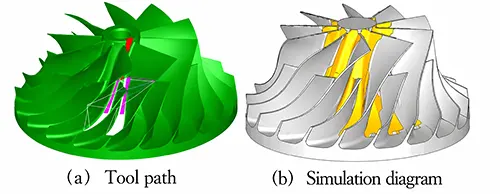
Semi-Finishing
Due to severe warping of the impeller blades, the residual height on the flow channel side walls after roughing is significant, forming a distinct “step” that can reach up to 2 mm at its highest point.
If not removed promptly, this will result in uneven cutting volumes during subsequent finishing operations, causing chatter, reducing surface quality, and even jeopardizing the service life of the cutting tools and spindle.
Therefore, semi-finishing involves smoothing the side walls of the blades to ensure uniform material allowance on the airfoil surface.
Table 5 lists the main parameters, and Table6 presents the results.
| Parameter | Leading Edge of Main Blade | Leading Edge of Splitter Blade |
|---|---|---|
| Feed rate / (mm·min⁻¹) | 2500 | 2500 |
| Feed amount / (mm·r⁻¹) | 0.125 | 0.125 |
| Cutting width / mm | 0.15 | 0.25 |
Table 5. Main Cutting Parameters for Semi-Finishing
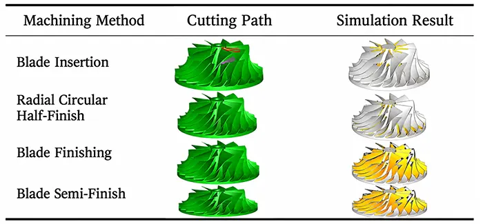
Finishing
Finishing is primarily used to ensure the precision of the diverter blades. Both the main blades and diverter blades of the impeller are straight-surface blades;
Using a side milling method can significantly improve machining efficiency, while high-feed spot milling for the flow channels and blade root fillets ensures the quality of the machined surfaces.
Operators perform finishing using the side milling method, which allows the entire blade to be finished in a single pass and delivers higher efficiency than spot milling.
The results are shown in Table 7.
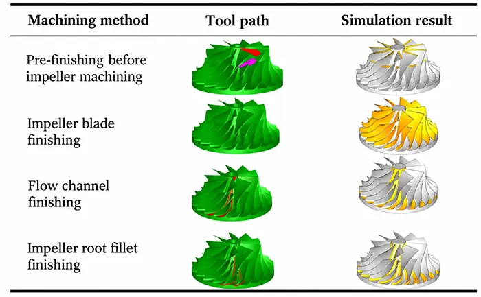
Post-processing and Analysis of Test Results
Engineers exported the machining operations configured in QJCAM as a CLS toolpath file, imported it into the pre-configured UG post-processor for post-processing, and converted it into an NC code file.
This NC code file was then used for post-processing and VERICUT simulation on the DMU 50 machine tool.
The final simulation results are shown in Figure 10.
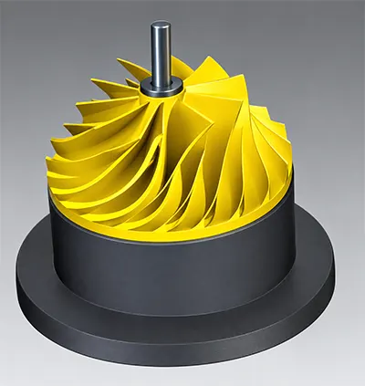
Using the VERICUT machining simulation module to examine the tool path, cutting allowance, and tool shank interference during the cutting process allows for a visual assessment of whether the tool path is appropriate, as shown in Figure 11.
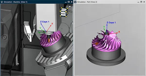
Import the 3D model into the QJCAM software, configure the tool parameters and select the milling mode, and complete the CNC programming for all steps—including roughing, semi-finishing, and finishing—before performing post-processing to obtain the final impeller, as shown in Figure 12.
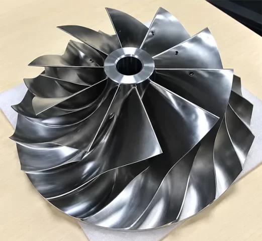
The results from the QJCAM software calculation show that the predicted machining time for the impeller is 1,110 minutes (approximately 19 hours), compared to 35 hours for the original plan, representing an 84% increase in efficiency over the previous plan.
Conclusion
This paper focuses on a complex impeller with diverter vanes.
Engineers used QJCAM to generate the CNC machining program and optimized the toolpath with this software.
The program was then imported into UG for post-processing to generate an NC code file for VERICUT machine tool simulation and actual machining.
The finished impeller closely matches the design dimensions and meets the precision requirements.
This optimized CNC machining process is of significant importance for breaking the technological and market monopolies held by foreign products, extending the service life of domestic cutting tools, and improving machining processes for difficult-to-machine materials.