
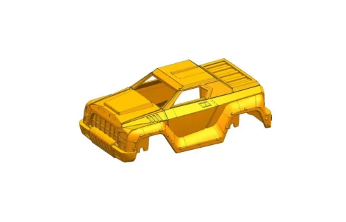





As a key pillar of the modern industrial system, the automotive industry relies on the performance, reliability, and lightweight design of its core component—the engine—which directly determine the overall quality and market competitiveness of the vehicle.
The valve cover is a critical sealing and functional component located at the top of the engine.
The valve cover performs core sealing functions by enclosing the valve train and preventing oil splatter as well as external contaminant ingress.
It also integrates multiple functional structures, including oil fill ports, oil-vapor separation channels, sensor mounts, and wiring harness mounting points.
Its performance directly impacts the engine’s sealing integrity, reliability, and Noise, Vibration, and Harshness (NVH) characteristics, as well as the overall aesthetic quality of the engine.
For plastic parts like valve covers—which feature complex structures, high precision requirements, and multiple integrated inserts—mold design is by no means a simple replication of cavities.
Rather, it is a complex systems engineering endeavor that integrates multidisciplinary knowledge, including materials science, polymer rheology, thermodynamics, and computer-aided engineering (CAE).
Several key factors determine whether the final product meets stringent technical requirements.
These factors include mold structure rationality, gating system optimization, cooling system efficiency, ejection system reliability, venting design adequacy, and specialized solutions for complex structures and inserts.
Structural Analysis of the Plastic Part
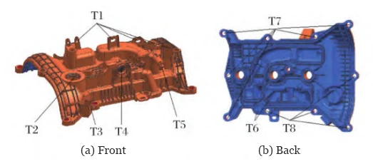
Figure 1 shows the structure of an automotive valve cover.
The plastic part is made of polyamide 66 (PA66) reinforced with 33% glass fiber (GF), with a shrinkage rate of 0.35%.
The overall dimensions of the product are 333 mm × 226 mm × 90 mm, with an average wall thickness of 2 mm and a volume of approximately 454 cm³.
The part requires high precision, meeting MT3 grade (GB/T 14486—2008).
The structural features on both the front and back surfaces of the part are relatively complex.
The structural ribs or latch features at position T1 on the front surface include multiple through-hole structures;
At position T2, there is a coarse-threaded feature with an M32 inner diameter and a pitch of 3.5 mm; at T3, there is a side hole feature on the product’s side rib;
At T4, the interior of the side hole features a fine-threaded M16 thread with a depth of 12 mm;
Position T5, there is a side tube structure with an inner diameter of 9 mm, an outer diameter of 15 mm, and a length of 35 mm;
At position T6, there is a 14 mm diameter angled hole feature serving as an oil return channel inside the valve cover.
Metal inserts are installed at all 10 through-hole locations at points T7 and T8.
These serve to reinforce the structure when the valve cover is bolted to the engine block, preventing deformation of the plastic part.
Additionally, this product requires high precision in its sealing surfaces.
These special geometric features not only significantly increase the technical complexity of material flow control during the molding process but also present multidimensional challenges for mold design and manufacturing.
Mold Structure Design
Design of the Gating System
This automotive engine valve cover is a medium-sized part produced in large batches, with high requirements for molding quality and dimensional accuracy.
Due to the complex structure on the cavity side of the part, it is not possible to inject material directly from the center of the part.
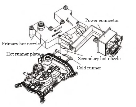
Figure 2 shows the structure of the plastic part’s gating system and the mold’s gating system in a hot runner-to-cold runner configuration.
The system uses a “hot runner plate + hot runner + cold runner” arrangement, and material ultimately enters the cavity through two fan-shaped cold gates on the side of the part.
Design of the Fixed Die Ejection Mechanism
Based on the analysis of the product structure shown in Figure 1, it is necessary to design corresponding ejection structures at the T1 and T3 features of the product to ensure smooth ejection.
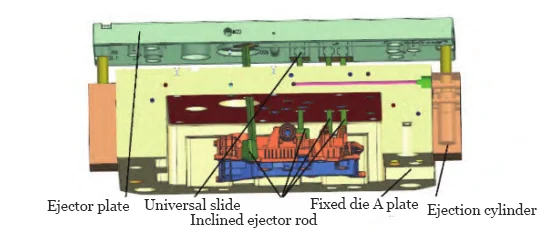
A “tilting ejector pin + slide block” mechanism is designed on the fixed die side.
Figure 3 shows the fixed die inclined ejector mechanism.
The ejector cylinder is mounted on Plate A of the fixed die, and the cylinder rod is connected to the ejector plate via screws.
The working stroke of the cylinder rod is 55 mm. Since the required core-pulling distance (s) for the product is small, the inclined ejector rod is designed with an angle of 5°.
Thus, s = 55 × tan 5° = 4.8 mm, which meets the requirements.
Dual-Link Rotary Core-Pulling Mechanism for T1 Side Holes
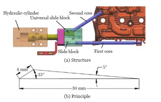
Figure 4 shows a dual-link pivot core-pulling mechanism.
The product surface at the locations of the two side holes on the T1 feature has numerous reinforcing ribs, leaving insufficient space to use an inclined ejector pin for demolding.
Therefore, an innovative demolding mechanism, as shown in Figure 4a, was designed.
Since the demolding directions of the two side holes are inconsistent, a conventional design would employ two hydraulic cylinders, which would increase the mold’s cost.
Here, a dual-linked rotary core-pulling mechanism is designed.
An universal slide block is incorporated within the slider connected to the hydraulic cylinder, enabling ejection in both directions through the movement of a single hydraulic cylinder.
The cylinder moves in the direction of the first core’s ejection, while the second core is secured to the slide via a screw.
The slide’s guide rails form a 5° angle with the slider’s direction of motion, and the hydraulic cylinder’s core-pulling stroke is 30 mm.
Consequently, the motion principle of the second core is shown in Figure 4b, with a 4 mm stroke sufficient to meet the demolding requirements.
Six-Lobe Retraction Mechanism for T2 Thread Feature
The T2 feature in Figure 1 is a threaded structure.
Conventional ejection mechanisms typically employ a “motor + gear” or “gear + rack” configuration;
Regardless of the mechanism used, both increase the mold’s volume and complexity.
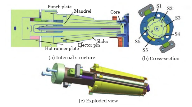
This paper designs a six-lobe retraction mechanism that utilizes the movement of the fixed mold’s ejector plate to achieve the retraction of the core at the threaded section.
Figure 5 illustrates the six-lobe retraction mechanism. As shown in Figure 5, the six-lobe retraction mechanism consists of multiple components.
It primarily includes a central hexagonal core shaft fixed to the hot runner plate, and a pusher block fixed to the fixed mold’s ejector plate.
Each side features a dovetail groove structure that forms a sliding pair with six inclined sliders (S1–S6).
Specifically, the inclination angles of sliders S1, S3, and S5 are 2.5°, while those of sliders S2, S4, and S6 are 5°.
Consequently, when the ejector block drives the sliders, the retraction distance of sliders S2, S4, and S6 is twice that of sliders S1, S3, and S5.
Design of the Moving Die Ejection Mechanism
As shown in Figure 1, the fine thread feature at T4 and the side tube feature at T5 of the product cannot be formed and ejected directly using a single slider.
Therefore, a three-stage ejection structure with a triple-stacked slider is designed for T4, and a two-stage ejection structure with a double-stacked slider is designed for T5.
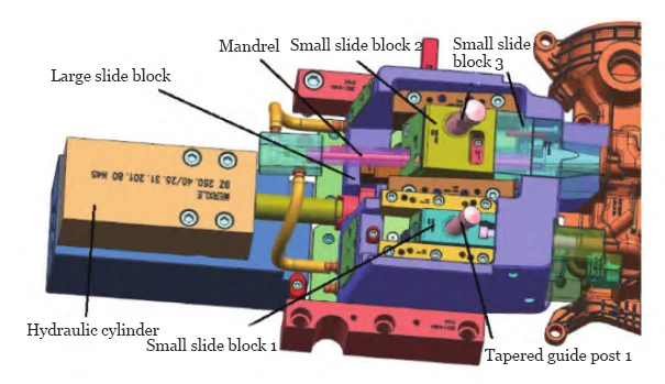
Both structures utilize the same large slider driven by a single hydraulic cylinder for core pulling.
Figure 6 illustrates the slider-within-slider ejection mechanism.
T4 Thread Feature Retraction Mechanism
As shown in Figure 6, a retraction mechanism for the thread feature at T4 is first designed.
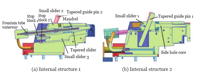
An inclined guide pillar 2 drives a core pin fixedly connected to small slider 2, thereby retracting the slider at the thread feature.
When small slider 2 contacts stop block 1, small slider 3 also performs a core-pulling motion under the continued drive of inclined guide pin 2, until small slider 3 contacts stop block 2.
At this point, inclined guide pin 2 also disengages from the slider.
To prevent the retraction mechanism from seizing due to temperature rise during operation, a fountain tube water channel must be designed inside the mandrel to cool it.
T5 Side Tube Core Pulling Mechanism
Figure 7 shows the internal structure of the multi-slider mechanism.
As shown in Figure 7, the side tube feature at T5 is formed using a side tube core.
During mold opening, the inclined guide pin 1 actuates the side tube core connected to small slider 1, enabling it to complete demolding.
After that, the hydraulic cylinder drives the large slider, completing demolding of the entire system.
T6 Inclined Hole Composite Interlocking Ejection Structure
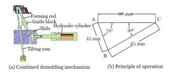
For the inclined through-hole feature at T6 on the back of the product shown in Figure 1, a composite interlocking ejection structure was designed, as shown in Figure 8.
As shown in Figure 8, this mechanism uses a hydraulic core-pulling cylinder to drive a slider.
The slider has a T-slot inside that is at a 30° angle to the horizontal plane.
The slide block at the bottom of the forming rod can slide along the T-slot, causing the forming rod to move in the core-pulling direction of the slanted hole.
The operating principle is shown in Figure 8b.
Segment AC represents the 89 mm travel distance of the hydraulic cylinder, while segment AB represents the 45 mm core-pulling distance of the forming rod.
The mechanism converts the inclined core-pulling motion of the forming rod into horizontal motion of the hydraulic cylinder.
This conversion reduces the dimensional requirements for inclined core-pulling components in the mold thickness direction and lowers manufacturing cost.
Design of the Ejector Mechanism for the Moving Die
The ejector mechanism of an injection mold primarily consists of a straight-ejector system and an inclined-ejector system.
The inclined-ejector system is generally divided into two types: split-type and integral-type.
A split-type inclined ejector consists of components such as an inclined ejector block, inclined ejector rods, guide sleeves, and universal slide blocks.
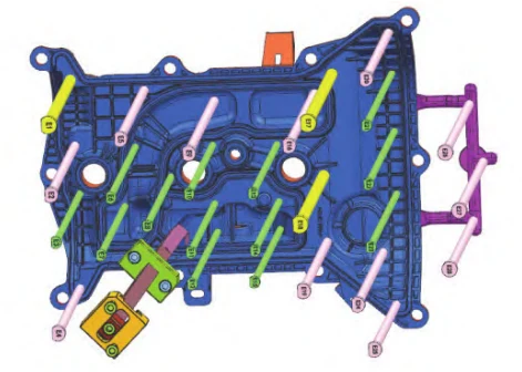
Figure 9 shows the design of the ejector system. As shown in Figure 9, the system combines inclined ejectors with straight ejector pins.
One square inclined ejector rod is guided by a copper block, which enhances the stability of the rod during movement; the working angle of the square inclined ejector rod is 8°.
The reverse side of the product features multiple reinforcing ribs, which generate significant clamping force on the core side during molding.
Therefore, 10 straight ejector pins with a diameter of 8 mm, 13 with a diameter of 6 mm, and 3 with a diameter of 10 mm are evenly distributed on the back of the product.
This ensures more uniform force distribution during ejection, preventing deformation caused by the ejector force.
Design of the Mold Cooling System
Automotive engine valve covers have complex geometries, and their molds feature intricate structures with numerous core-pulling mechanisms.
To prevent mechanical jamming or damage caused by mold overheating, the water channel layout must be balanced.
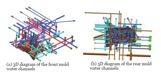
Figure 10 shows the design of the mold cooling system.
As shown in Figure 10, in the cooling design of the front mold, each slider has a large contact area with the product, resulting in significant heat exchange.
Therefore, a set of 8 mm diameter circulation loops is designed inside each slider;
In the six-petal retraction mechanism of the fixed mold, a set of “fountain tube” cooling channels with an inner diameter of 4 mm and an outer diameter of 6 mm is designed to enhance the cooling of the core pins;
The cavity side of the front mold includes five sets of conformal cooling channels.
Each set combines “through-type + well-type” channels, where the through-type channels measure 10 mm in diameter and the well-type channels measure 16 mm in diameter.
Multiple cylindrical inserts and numerous ejector pin arrangements exist on the core side of the moving mold.
To avoid interference between these components and the cooling channels, the design incorporates three sets of “through-type + well-type” combined cooling channels within the core.
The optimized cooling channel design promotes more uniform shrinkage during the molding process.
It also prevents excessive product deformation and reduces cycle time while improving production efficiency.
Assembly Drawing and Operating Principle of the Mold
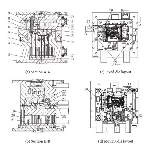
Figure 11 shows the structure of an injection mold for an automotive engine valve cover.
As shown in Figure 11, the mold employs a single-point hot runner-to-cold runner injection system.
During mold opening, synchronized ejection cylinders drive the synchronized ejection movement of the fixed mold side’s ejection mechanism.
With dimensions of 900 mm × 900 mm × 920 mm, this mold is classified as a medium-to-large precision injection mold. The mold’s operating process is as follows:
(1) Hot Runner to Cold Runner Melt Flow Path in Injection Molding
Melted plastic flows through the primary hot nozzle and moves into the hot runner manifold.
It then passes into the secondary hot nozzle 9 and enters the mold cavity through the cold runner located on the parting line.
(2) Core-Pulling and Ejection Sequence in Mold Opening Process
Once the melt has filled the cavity, the product fully solidifies after holding pressure and cooling;
First, the core-pulling cylinder 25 on the fixed mold side completes the ejection of the product at point T1 via an interlinked rotary shaft mechanism;
Then the mold begins to open slowly, while the ejector cylinder 29 drives the fixed mold ejector plate 13 to move;
At a travel distance of 65 mm, the fixed mold ejector plate 13 reaches its set limit position.
At this point, all fixed mold-side ejection mechanisms finish the core-pulling motion, and the ejector cylinder 29 stops its movement.
(3) Moving Mold Core-Pulling and Product Ejection Process
After the moving mold has fully opened and comes to a stop, the two core-pulling cylinders on the moving mold begin to move, completing the core-pulling action required for the product.
The injection molding machine’s ejector pins act on the ejector base plate 18 and the fixed plate 17 through the threaded connecting rod 26.
This motion drives the ejector pins and ejector tubes forward, forcing the product out of the moving mold cavity.
(4) Mold Reset and Closing Cycle Process
Once the molded part is completely ejected, the injection molding machine’s ejector rod resets the ejection system via the threaded connecting rod 26.
Next, the core-pulling cylinders on the moving and fixed molds return to their home positions, followed by the ejection cylinder 29 on the fixed mold.
Finally, the mold closes to prepare for the next injection molding cycle.
Conclusion
The mold employs a system structure that transitions from a single-point hot runner to a cold runner, which not only reduces manufacturing costs but also meets the requirements of injection molding.
The mold utilizes a two-point side gate for material injection, thereby reducing injection pressure. Multiple ejection mechanisms are designed on the fixed mold side;
Through ejector cylinders installed on both sides of the fixed mold A-plate, the ejection mechanisms are activated synchronously during mold opening.
Hydraulic cylinders drive multiple composite core-pulling mechanisms on the moving die side.
These mechanisms adopt a “slider-within-slider” configuration to handle demolding challenges in specific local features of the product.
The mold’s cooling system incorporates an interlaced conformal cooling channel network to reduce the injection molding cycle time.
Following actual trial runs, the dimensional accuracy of the molded parts met MT3 requirements.
The mold’s structural design is reliable, and all demolding mechanisms function effectively.