
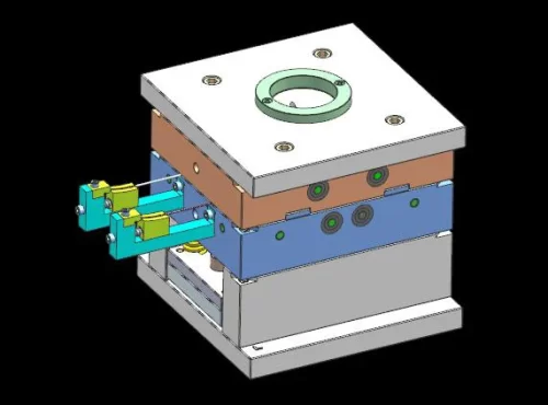





With advancements in plastic materials, molding technologies, and manufacturing processes, the application of plastic products has evolved from ordinary decorative components to structural and functional parts, and the demand for injection-molded products in the consumer goods market has been growing year by year.
In developed countries such as Germany, the United States, and Japan, plastic products are already widely used in fields such as aerospace, automotive, home appliances, and 3C products.
The domestic Chinese market has also set new requirements for the appearance, internal structure, and performance of plastic products, placing increasingly higher demands on the development of plastic molds.
Plastic mold design and manufacturing require comprehensive consideration of multiple key factors.
These include the selection of parting lines, the design of the gating system, and the configuration of core-pulling mechanisms.
In addition, CAE analysis guides the optimization of the cooling system as well as mold assembly and trial-molding process parameters.
Product Analysis
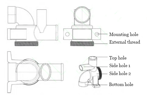
Figure 1 shows a plastic valve body component. The part has a maximum length of 107 mm, a maximum width of 80 mm, and a maximum height of 84 mm.
The average wall thickness is 1 mm, with the thickest section measuring 2.8 mm.
The part features numerous details and requires high dimensional accuracy.
It includes 1 top hole, 1 bottom hole, 2 side holes, 2 assembly locating holes, and 1 external threaded pipe connector.
The part’s surface must be smooth, necessitating precision machining of the mold’s forming components, particularly the cavities.
Several structural features of the part require mating with other components; the assembly must not be loose or too tight.
This places higher demands on the mold’s core-pulling mechanism, ejection mechanism, and water channel design, as well as on assembly positioning and clamping.
Overall Mold Design
Structural Layout
The part has a complex structure. If a horizontal layout is adopted, it would require four lateral core-pulling mechanisms and thread-forming features.
The mold structure would be complex and relatively large, making it difficult to ensure orderly movement of the core-pulling mechanisms.
If a vertical layout is adopted with an auxiliary clamshell molding method, two core-pulling mechanisms would be required, and the mold structure would be relatively simple.
After comprehensive evaluation and consideration of the customer’s actual needs, a vertical layout with a single cavity per mold was selected.
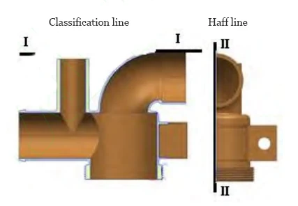
The product layout is shown in Figure 2.
The threads at the bottom end of the part are formed using a half-slider mechanism to ensure a compact structure and simple assembly relationships.
The mold structure employs two parting lines: the first I-I parting line is located on the top surface of the part, primarily to facilitate the removal of solidified material from the runner system;
The second II-II half-slider parting line is positioned at the symmetrical center of the part, primarily to facilitate the formation of the threads at the bottom end of the part.
CAE-Assisted Design of the Gate System
The part is molded from PE plastic, which offers excellent molding properties, superior flowability, uniform material temperature, and fast filling rates.
A single-point cold gate and cold runner system can be adopted for the gate system.
The CAE gate location analysis report and the above evaluation provide the basis for the design decision.
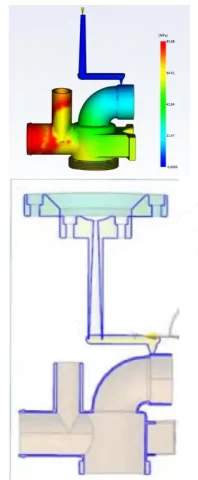
The design adopts the single-gate cold runner system shown in Figure 3. The gate and runner are positioned at the intersection of the parting line and the half-line.
Figure 3 shows the gate location cloud plot analysis results. These results indicate that the gate design achieves uniform filling of the molten plastic.
It also maintains a relatively stable flow front throughout all stages of the injection molding process.
Additionally, the gate is positioned near the junction of the part’s side surface and end face.
This design offers three advantages: first, it does not affect the surface quality of the part; second, it facilitates the removal of gate flash;
And third, it simplifies the machining of the runner and gate.
Design of Molding Components
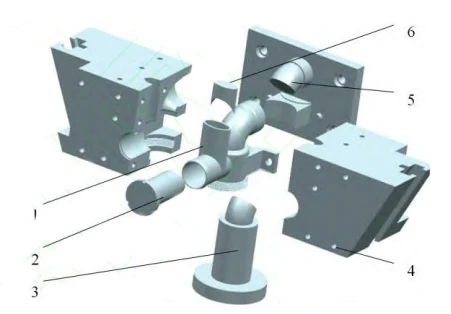
Due to the complex structure of the part, the molding components shown in Figure 4 were designed to accommodate its structural characteristics.
They consist of a lateral long core, a main core for the moving and fixed dies, a lateral core assembly, and a half-slider.
Since the core shapes in this example are relatively complex, all molding components employ an insert-type modular structure to facilitate machining and heat treatment.
Hydraulic Core-Ejection System and Structural Constraints
Additionally, the product features deep lateral holes and a significant lateral ejection distance, resulting in substantial clamping force on the opposing core.
To ensure a compact mold structure and safe, orderly, and reliable core ejection, this mold requires a hydraulic core-ejection mechanism, with the ejection motion controlled by limit switches in the hydraulic system.
Wear Risk and Assembly Precision Requirements
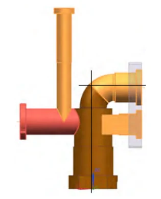
During mold opening, the left lateral core comes into contact with the fixed mold’s main core.
At the same time, the right lateral core assembly contacts the moving mold’s main core, as shown in Figure 5.
Friction occurs at the contact surfaces, causing the cores to wear easily and increasing the clearance between them.
This results in flash, which ultimately affects the molding quality of the product.
During mold assembly, positioning and clamping devices are required. These devices improve assembly accuracy and reduce or eliminate friction between components.
They also prevent loosening of the mold over extended use, which helps maintain the quality of the molded parts.
Sequential Core-Pulling Control and Half-Slider Timing Strategy
The mold opens, and the left lateral long core and right lateral combination core apply a higher clamping force than the half-slider.
As a result, the part tends to move together with the lateral cores during the initial opening stage of the mold.
This can potentially damage the part’s surface or even strip the threads.
The design takes advantage of the time difference between the separation of the lateral cores and the half-slider. While the lateral cores are still moving, the half-slider remains engaged and has not yet separated.
This action keeps the part restrained and prevents it from moving along with the lateral cores.
Once the lateral cores have retracted, the half-slider then separates.
During closing, the half-slider returns to its original position first, followed by the lateral cores.
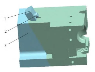
As shown in Figure 6, the half-slider completes the lateral mold opening motion outward under the action of the T-shaped guide rail 7.
During mold closing, the half-slider returns to its original position first, with the return stroke controlled by a limit screw.
CAE-Assisted Mold Cooling Channel Design
The design of cooling channels requires comprehensive consideration of factors such as mold structure, part geometry, wall thickness, and product warpage.
The quality of the cooling channel design directly affects the molding quality and cycle time of the product.
The process uses PE plastic as the molding material for this product. Its high shrinkage rate, together with the large size of the half-slide sliding block, creates specific cooling demands.
Designers add conformal cooling channels to the half-slide along the direction of maximum shrinkage to improve cooling efficiency.
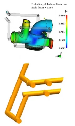
CAE software optimizes the layout of the cooling system, producing the cooling channel design shown in Figure 7.
The design specifies a 10 mm channel diameter and includes machined clearance grooves for the inlet and outlet pipes in the platen.
The CAE flow, cooling, and warpage analysis report indicates that this channel design enables rapid and uniform cooling of the part while minimizing warpage deformation.
Operators consider operational convenience during mold installation.
The injection molding machine arranges the inlet and outlet water line connections on the side of the mold opposite the operator to improve handling and accessibility.
Design of the Mold Ejection Mechanism
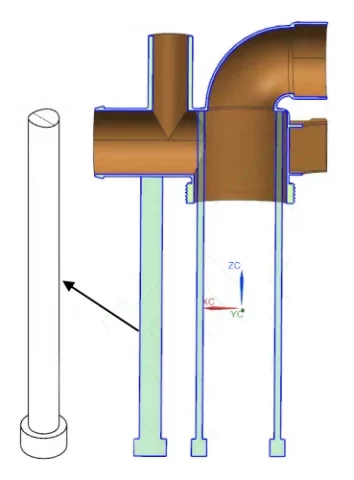
While ensuring a uniform distribution, the ejector pins should be positioned at locations with the highest demolding resistance.
This example takes into account the tubular structure of the part.
It also considers the machining requirements of the ejector pin working surfaces and the rigidity requirements. Based on these factors, the ejector pins shown in Figure 8 are designed.
The smaller ejector pin sits at the step inside the tube and has a diameter of 10 mm.
The larger ejector pin sits at the center of the left-side tube wall of the part and has a diameter of 40 mm. Its working end face transitions smoothly into the arc of the tube surface.
An ejector pin mounting plate secures the ejector pins.
Mold Operating Process
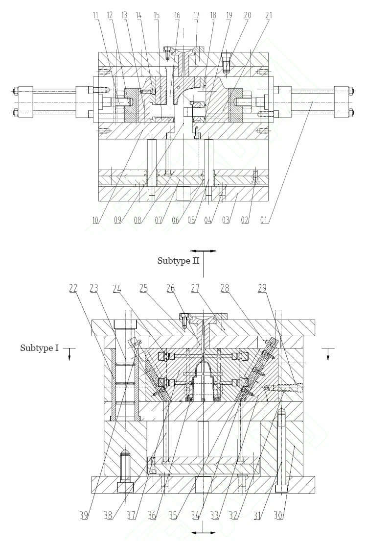
Figure 9 shows the assembly drawing of an injection mold. The specific operating process is as follows:
(1) Mold Clamping and Machine Installation Procedure
The operator clamps the mold, lifts it into the injection molding machine, and secures it with a clamping plate.
(2) Injection Molding, Holding Pressure, and Cooling Process
The injection molding process starts with filling, then proceeds to holding pressure and cooling.
After completing the injection, cooling, and holding pressure phases, the system prepares the mold for opening.
(3) Mold Opening Sequence and Half-Slider Release Mechanism
When the mold opens, the injection molding machine drives the moving mold section backward.
Opening starts at the I-I parting line position of the mold. At the same time, spring force drives the T-shaped blocks 37 (half-sliders) to move diagonally upward on both sides along their guide direction.
This motion separates the molding surface from the product’s mold cavity.
The movement stops at the position of the stop pin 39;
(4) Hydraulic Core-Pulling Operation and Slider Movement Control
After the injection molding machine opens to a certain stroke, the machine’s control unit receives a position signal and begins supplying oil to the cylinders of the left and right sliders (13 and 21).
Driven by the core-pulling force from cylinder 01, the left and right sliders move sliders 13 and 21 outward to either side, separating them from the product.
The core-pulling distances are 66 mm and 37 mm, respectively, controlled by limit switches;
The hydraulic system controls the ejection time and stops the movement when the limit position is reached.
(5) Ejection Mechanism Activation and Product Removal
The injection machine’s ejector rod moves forward.
Under the action of the ejector rod, the mold ejection mechanism (07/08/38) ejects the plastic product clamped onto part 9 along with the sprue material;
(6) Mold Reset and Closing Cycle Sequence
After removing the plastic product, the mold begins to reset, and the injection machine retracts the ejector rod.
A reset signal triggers the hydraulic cylinders 1 on both sides as the mold prepares to close.
The cylinders extend their piston rods forward, driving sliders 13 and 21 forward until both return to their original positions.
At this point, the injection machine’s rear mold moves forward, the moving die section moves forward with the injection molding machine’s rear die.
Once the rear die return rod contacts the front die, it pushes the mold ejection mechanism backward to reset.
After contacting the fixed die base plate 27, the clamping block begins to move.
It travels diagonally downward along the guide rails of the clamping T-block 34 and continues until reaching the reset position, where the motion stops.
At this point, the mold completes its reset and closes, and the next injection molding cycle begins.
Conclusion
CAE technology drives the design of a mechanism capable of multi-directional core pulling.
Hydraulic core pulling enables long-distance core movement within the mold structure. A half-slider forms the external thread features of the product.
Sequential parting coordinates the core-pulling actions, preventing interference between mechanisms and maintaining product quality.
It is suitable for molding products with external threads and applications requiring multi-directional core pulling, and is particularly suitable for molding valve bodies and other household appliance injection-molded products .
The results demonstrate that this injection mold features a compact design and orderly core-pulling mechanism, providing a reference for the structural design of injection molds for plastic products with similar characteristics.