

As the core power component of a hydraulic transmission system, the operational stability and transmission efficiency of the oil pump directly determine the operating conditions of the entire machine.
The oil pump gear is a critical core component of the fuel system’s powertrain.
During engine operation, the oil pump gear must transmit significant loads, and the uniformity of force distribution across the gear tooth surfaces significantly affects the gear’s service life and the oil pump’s unloading performance.
As a critical structural feature of the oil pump gear, the unloading groove effectively mitigates hydraulic shock during tooth engagement, reduces fluid vortex losses, and minimizes tooth surface wear, thereby enhancing the operational reliability of the oil pump.
Consequently, the machining quality of the unloading groove has become a key factor limiting the performance of the oil pump gear and, by extension, the entire machine.
This paper investigates a new machining method for a novel type of relief groove.
This new relief groove structure sits at both ends of the tooth flank and extends its shape along the tooth profile.
Machiners encounter certain challenges when machining this structure for the first time.
Traditional machining methods struggle to balance machining efficiency and precision, failing to meet the performance requirements of high-precision oil pump gears.
Consequently, this paper focuses on the key technologies for machining relief grooves on the tooth faces of oil pump gears.
It examines the machining process, machining programs, cutting tools, machining parameters, and alignment methods for milling grooves on involute surfaces to explore effective machining approaches.
The aim is to overcome the challenges in relief groove machining, improve machining quality and efficiency, and provide technical support for the production of high-precision oil pump gears.
Problem Description
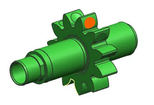
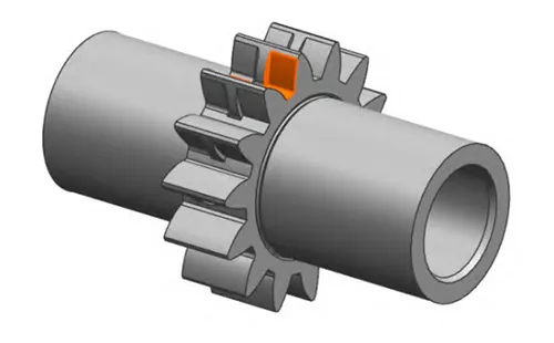
Figure 1 shows a new type of relief groove added to the tooth profile surfaces of the driving and driven gears.
Figure 2 illustrates the original relief grooves, which occupy the center of the tooth profile surface and extend along the tooth direction.
The new relief grooves sit at both ends of the tooth profile surface and also extend along the tooth direction.
Machiners encounter several machining challenges when producing this structure for the first time, as described below:
① Ensuring the symmetry of the relief grooves: Since the relief grooves are located at both ends of the tooth profile, meshing after profiling relies solely on the central portion of the tooth profile.
Therefore, to ensure smooth meshing, the relief groove dimensions must be consistent between the driving and driven gears.
Consequently, the scheduling of the relief groove milling operation in the manufacturing process must guarantee this requirement.
② Machining alignment during relief groove milling: It is necessary to quickly align the gear center and ensure consistent machining alignment for each tooth.
③ Programming of the machining sequence: Relying solely on the differences between the gear section in the 3D model and the actual gear on the part will result in relief grooves that do not match the model;
Operators adjust and optimize the toolpaths accordingly.
④ Tool interference and the impact of tool selection on machining efficiency: Each part has 14 teeth, with two relief grooves per tooth, for a total of 28 relief grooves;
Operators boost the machining efficiency.
Root Cause Analysis
Analysts adopt a cause-and-effect diagram to examine defects encountered during relief groove machining on oil pump gear tooth faces;
Low machining accuracy and unsatisfactory surface quality serve as the core problem indicators.
They trace the root causes from five dimensions: operator, machine, material, process method, and working environment.
The primary causes of these issues are as follows:
The Unique Characteristics of the Relief Groove Profile on the Gear Tooth Surface
The original relief groove on the gear tooth surface sits at the centre of the tooth profile and extends along the tooth direction.
Machining follows a linear path along the gear tooth direction (the central axis of the workpiece) for both tool trajectory and dimensional control.
By contrast, the new relief groove structure occupies both ends of the tooth profile surface and extends along the tooth profile direction.
The machining path and dimensions follow the involute curve of the gear’s tooth profile surface.
During machining, the influence of the tooth profile’s involute structure must be taken into account.
Each relief groove distributes uniformly and retains specified angular relationships.
Machiners encounter notable technical challenges when machining this newly adopted structure for the first time.
Angular Positioning of the Part
When machining surfaces that have an angular positional relationship with the teeth, it is difficult to determine the machining center of the teeth during the process.
Generally, machining these types of surfaces requires specific auxiliary fixtures.
Furthermore, due to the unique nature and diversity of gear components—where variations in module and number of teeth necessitate different fixtures—the tooling is typically limited to dedicated setups.
This means that a single part requires the design of a dedicated fixture;
It is not possible to design a universal fixture capable of machining all such surfaces.
In actual machining, the manufacturing costs of these dedicated fixtures are usually very high.
Improvement Measures and Validation
Process Flow Planning
Analysts consider the gear material properties and dimensional accuracy requirements and carry out analysis from the following three aspects.
They formulate a suitable process flow that balances efficiency and accuracy to guarantee machining quality.
1. Analysis of Material Properties
The part material is the powder metallurgy grade HOP10V, a high-vanadium tool steel.
It contains numerous carbides and hard particles, has a high vanadium content, and exhibits excellent wear resistance.
The hardness of the hard particles in the microstructure reaches HRC 65–70. These hard particles can cause severe and rapid tool wear.
Furthermore, the material’s porosity means that, from a microscopic perspective, machining the part is equivalent to intermittent cutting;
Consequently, tool wear is severe during machining.
Therefore, wire-cut EDM is employed for rough machining of the tooth profiles.
2. Analysis of Gear Machining Accuracy
Machiners select the tooth profile surface as the alignment reference for machining, because the relief grooves sit on this surface and must meet specified dimensional and angular tolerances relative to it.
They arrange gear grinding after wire EDM of the teeth to secure gear accuracy, including normal tooth thickness W, radial runout of the gear ring Fr, tooth profile tolerance and helix angle tolerance Fβ.
This step ensures symmetric and consistent machining of relief grooves.
3. Analysis of Gear Tooth Width Accuracy
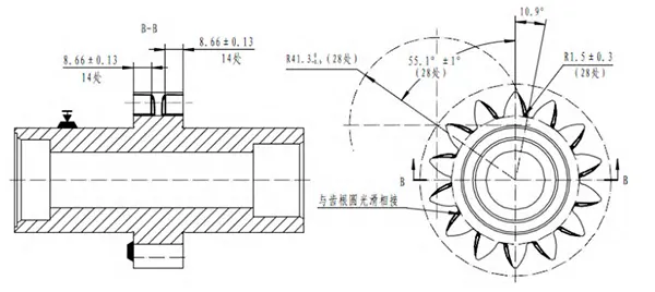
The dimensions of the relief grooves are shown in Figure 3.
During machining, one end face of the gear is used for positioning, and the relief grooves on both ends are machined in a single setup.
This requires excellent consistency in the part’s tooth width dimensions to ensure the uniformity of the relief grooves.
Machiners prioritize the consistency of tooth width dimensions because the driving and driven gears work as matched pairs.
They satisfy this critical requirement while setting the machining datum.
In summary, technicians need to scientifically coordinate t
he machining process for relief grooves on oil pump gear tooth surfaces:
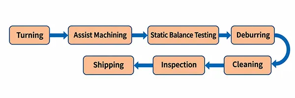
They first rough-machine the blank, then machine the datum surfaces to secure positioning accuracy, and finally perform milling to meet the dimensional tolerance requirements of the relief grooves.
Figure 4 illustrates a typical process flow.
Creation of the 3D Model
The 3D model must be based on the actual dimensions of the gear after rough grinding; the design model cannot be used directly.
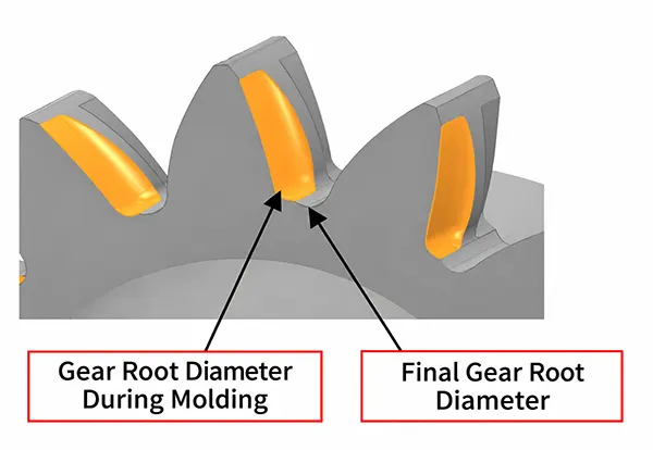
This ensures precise positioning of the tooth profile, guarantees the relative position of the machined relief groove to the tooth profile, and ensures a smooth transition to the tooth root.
In other words, modelers construct the involute surface of the gear using the practical machining dimensions of the part, as listed in Table 1.
By contrast, they build the relief groove geometry following the final dimensions defined on the design drawings, as illustrated in Figure 5.
| Gear Parameter | Nominal Dimension | Final Machined Dimension |
|---|---|---|
| Common Normal Length | 38.76 | 38.56 |
| Root Circle Diameter | Ø60.7 | Ø60.65 |
| Tooth Tip Circle Diameter | Ø83.2 | Ø82.94 |
| Tooth Root Fillet Radius | R1.8 | R1.8 |
Table 1. Dimensions of the Rear Gear Section Before and After Keyway Milling (mm)
CAM Programming and Tool Selection
The primary objectives of CAM programming are to optimize toolpaths and select the best machining strategy, thereby reducing the number of idle passes and minimizing unnecessary tool movements to improve machining efficiency.
1. Selection of Machining Type
Analyze the structural characteristics of the part and the geometric features of the machining areas.
Select a fixed contour for machining. Taking into account tool wear and machining accuracy during the process, divide the machining into roughing and finishing steps.
Use surface-area-driven machining, selecting the relief groove as the driving geometry.
For roughing, select unidirectional cutting mode (since the stock allowance is large at this stage, unidirectional cutting results in less tool wear;
Set the residual height to 0.006). for finishing, select unidirectional cutting mode (since the allowance is small and tool wear is minimal;
Choose a reciprocating cutting mode with a residual height of 0.002 to better ensure machining accuracy and achieve higher machining efficiency);
Select the tool axis as the projection vector, and define the vector as the tooth centerline.
2. Tool Selection
Due to the limitations imposed by the size of the tooth grooves, consider using a larger-diameter ball-nose end mill for machining, provided there is no interference.
Machining specifications define a transition radius of R1.5 ± 0.3 at the relief groove root, so technicians directly select a Φ3 ball-nose end mill.
This tool supplies the required transition radius R, prevents interference, and maintains favourable tool rigidity.
3. Programming Techniques
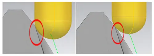
During the programming process, the first test run revealed that the first cut resulted in a tool gouge, causing the tool to break.
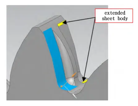
Analysts identify the curved machining surface as the root cause; this surface creates an excessive material allowance for the first cut of the generated toolpath.
Researchers perform analysis and verification. Programmers extend the workpiece ends along the original curved-surface trajectory.
They choose this extended plane when they define the drive geometry (see Figure 6).
The system generates a new machining path. This path removes the tool-digging-in defect on the first cutting pass (see Figure 7).
In summary, CAM programmers leverage 3D models to arrange toolpaths rationally and refine cutting parameters.
They specify appropriate feed rates and cutting depths, define tool motion trajectories, and select matching cutting tools.
This process ultimately yields optimal machining parameters, providing reliable data support for efficient and precise machining on machining centers.
The specific parameters are shown in Table 2.
| Machining Method | Tool Diameter (mm) | Spindle Speed (r/min) | Feed per Tooth (mm/tooth) | Radial Depth of Cut (mm) |
|---|---|---|---|---|
| Rough Milling | Ø3 | 2800 | 0.05 | 0.8 |
| Finish Milling | Ø3 | 3000 | 0.02 | 0.1–0.2 |
Table 2. Machining Parameters Before Keyway Milling
Determining the Part Alignment Method for Machining
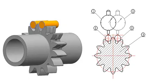
During the machining process, to accurately locate the centerline of the gear, the pin-type gear-face alignment method is used, as shown in Figure 8.
Taking a vertical machining center as an example, operators clamp Part 3 onto the machine’s A-axis before machining and position two roller bars 2 between adjacent gear teeth according to dimensional calculations.
For alignment, technicians first carry out rough positioning with a height gauge, then use a dial indicator 1 to finely align the highest points of the two roller bars and keep them horizontal.
This improves alignment efficiency, saves alignment time, and ensures that the centerline of the part’s teeth aligns with the machine’s A-axis.
At this point, the centerline of one tooth between the two roller bars serves as the origin; the programming origin must match this origin.
After machining each tooth profile, rotate the workpiece by an angle calculated as 360°/Z to proceed to the next tooth.
Operators repeat this procedure to machine relief grooves on all tooth profiles.
The contact point between each roller bar and the tooth surface should lie close to the gear pitch circle, and the outer diameter of the roller bar must exceed the addendum circle for convenient alignment.
The rolling bar diameter can be selected using the formula dp = (1.68–1.9) m.
This calculation yields the optimal dimensions for the rolling bar used in actual alignment.
Under normal circumstances, a standard pin of similar dimensions may be used as a substitute.
Since indexing is based on the gear pitch circle, this ensures that the machined area maintains accuracy and stability relative to the entire gear component throughout the gear’s operation.
Conclusion
This paper provides a scientific and comprehensive overview of the machining process for relief grooves on the tooth profiles of oil pump gears.
The process begins with rough machining of the blank, followed by machining the reference surfaces and gear tooth profiles to ensure positioning accuracy, and concludes with milling.
This study examines two key influencing factors. These factors are clamping and positioning schemes, and machining strategies.
Engineers analyze how these factors affect part accuracy. The work guarantees dimensional precision of relief grooves.
It also builds a standardized process workflow. Programmers rationally plan toolpaths, configure proper cutting parameters, define clear tool trajectories and select suitable cutting tools via CAM programming.
Technicians adopt the pin-based tooth-surface alignment method to locate gear tooth surfaces and strictly control accuracy at each step, guaranteeing the forming quality of relief grooves.
This effectively improves machining efficiency, meets operational requirements, and provides a reliable foundation for optimizing gear machining processes.