
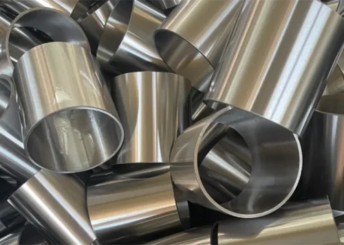

Bushings serve to support, reduce friction, transmit torque, and center components in machinery such as automobiles and machine tools.
Their dimensional accuracy, shape, positional accuracy, and surface roughness significantly affect the working precision, smooth operation, and service life of these components.
Modern manufacturing places higher demands on bushings, and traditional fixtures are no longer sufficient to meet these requirements.
Currently, the main challenges in high-precision bushing machining include: large cumulative errors and low efficiency resulting from improper process planning;
Deformation of thin-walled parts caused by clamping forces; and unstable errors during batch production.
The positioning stability and clamping reliability of fixtures are crucial; however, traditional dedicated fixtures are specialized and bulky;
Standardized fixtures, on the other hand, struggle to meet high-precision requirements, creating a conflict between flexibility and specialization.
Therefore, systematically optimizing machining processes and innovatively designing supporting fixtures holds significant theoretical and practical value.
This study adopts advanced process theories and innovative fixture design methods.
It addresses the technical difficulties encountered during high-precision bushing machining.
The outcomes can deliver practical technical solutions for related enterprises.
Enterprises can use these solutions to raise product quality, cut production costs, and strengthen their market competitiveness.
Systematic Optimization Strategies for High-Precision Sleeve Machining Processes
Process optimization is a prerequisite for improving machining quality.
This study will develop a systematic set of process optimization strategies based on four dimensions: process sequence, machining methods, parameter control, and error compensation.
Rearrangement of Process Routes and Optimization of Process Integration
Traditional serial process routes are the primary cause of inefficiency and errors.
The key to optimization lies in “reducing the number of setups and implementing combined machining.”
First, conduct a value stream analysis of the existing processes to eliminate unnecessary steps.
For example, for sleeve-type parts with high coaxiality requirements, the principle of “single setup, multiple-surface machining” should be followed.
We formulate the process route as follows. We use the blank outer diameter for roughing alignment.
A single clamping setup completes rough machining for the end face, outer diameter, and inner bore.
For subsequent operations, the workpiece relies on two pre-machined precision datums: an end face and the inner bore.
Operators perform finish turning of the outer diameter, groove milling, and drilling on a turn-milling center.
This reduces the number of setups to 2–3, thereby minimizing errors caused by misalignment of reference surfaces.
Precision Machining Methods for Critical Processes
For critical dimensions that affect the quality of bushings, it is necessary to determine appropriate precision machining methods.
We can arrange the machining sequence of internal bores in this order: rough boring, semi-finish boring, and finish boring.
We remove material in separate stages and boost accuracy step by step.
Manufacturers select high-hardness, wear-resistant materials like PCD (polycrystalline diamond) or CBN (cubic boron nitride) for cutting tools.
Operators must tightly limit tool tip runout to guarantee machining accuracy.
High-pressure emulsified coolant should be used for forced cooling and chip removal to prevent thermal deformation.
For ultra-high-precision outer circles or inner bores, precision grinding or honing should be added as the final machining process after fine boring or fine turning.
For example, the ϕ38–0.036 mm bearing mounting surface of a large hollow bushing was ultimately ground to ensure precision.
Operators choose a high-precision grinding machine for grinding operations.
They optimize and coordinate the grinding wheel linear speed, workpiece rotational speed, and feed rate.
Sufficient grinding fluid must be applied to achieve a surface roughness of Ra ≤ 0.2 μm and a roundness of ≤ 0.003 mm.
Machining Parameter Control Strategies
Precise control of machining parameters is essential for achieving machining accuracy and stability.
Based on the machining methods established in the previous sections, this subsection systematically discusses the control of key parameters.
Precise control of machining parameters is essential for achieving machining accuracy and stability.
We assign distinct cutting parameters to every internal bore boring stage.
Rough boring uses a spindle speed of 800–1,200 r/min, a feed rate of 0.15–0.2 mm/r, and a machining allowance of 0.3–0.5 mm.
Semi-finishing modifies these settings: the spindle speed rises to 1,500–2,000 r/min, the feed rate reduces to 0.1–0.12 mm/r, and the allowance decreases to 0.08–0.12 mm.
Finish boring employs a spindle speed of 2,500–3,500 r/min paired with a feed rate of 0.05–0.08 mm/r.
This shallow cutting depth limits heat buildup throughout the machining process.
Regarding tool parameters, the radial runout of the tool tip must not exceed 0.001 mm;
When used with PCD or CBN inserts, this ensures a dimensional accuracy of ±0.005 mm.
We adopt high-pressure emulsion for cooling. Its pressure stays at no less than 5 MPa.
We spray this fluid directly onto the cutting zone for forced cooling and reliable chip evacuation. Operators optimize precision grinding parameters holistically.
These parameters include the grinding wheel linear speed, workpiece rotational speed, and feed rate.
Practitioners determine the exact values through tests.
They consider both the workpiece material and the grinding machine’s actual performance. We also maintain sufficient grinding fluid supply.
This setup helps us reach the target specifications: surface roughness Ra ≤ 0.2 μm and roundness ≤ 0.003 mm.
We control all these parameters systematically. This control stabilizes the machining process and preserves its accuracy.
Combined with the machining approaches introduced in this paper, these measures build the core of our integrated process optimization strategy.
Techniques for Preventing and Compensating for Machining Errors
Building on the parameter controls described above, active error compensation is necessary to ensure stability in mass production.
We prioritize thermal deformation control. Fully preheat the workpiece, cutting tool and machine tool before machining under a constant temperature of 20±2°C.
Monitor spindle temperature rise continuously during cutting. Reduce the spindle speed by 10%–15% once the temperature increment exceeds 5°C.
Tool wear compensation serves as the next control strategy. Derive compensation amounts from online measurement results or production batch counts.
Activate compensation at regular intervals, such as after machining every 200 workpieces. Adjust the boring tool tip position subtly by 0.001–0.002 mm per compensation cycle. Statistical Process Control (SPC) forms the final safeguard.
Inspectors sample key dimensions including inner diameter on an hourly basis.
They construct mean–range control charts to evaluate process capability.
The system issues instant warnings upon abnormal signals, and technicians investigate underlying causes without delay.
Innovative Fixture Design for High-Precision and High-Efficiency Clamping
Fixtures serve as the physical means for implementing process solutions.
This study proposes an innovative fixture structure that integrates the concept of “single-step positioning and sequential clamping,” and details its design steps and key technologies.
Design Requirements Analysis and Proposal of Innovative Concepts
Based on the aforementioned process requirements, the design of this new fixture must adhere to the following basic principles. First, precise positioning.
The positioning error should be less than one-third of the workpiece tolerance;
We take the symmetry tolerance of a hole as an example. If the tolerance value is 0.12 mm, the fixture positioning error must stay below 0.04 mm.
Second, we design clamping schemes to limit workpiece deformation.
Thin-walled sleeves easily deform under clamping force. We spread clamping force uniformly and make the force adjustable.
Third, we prioritize fixture versatility. The fixture supports multiple machining tasks on one workpiece, including internal boring and outer turning.
This design avoids repeated positioning. Fourth, we balance convenient operation and structural rigidity. Operators can load and unload workpieces quickly.
The whole fixture structure holds enough rigidity to damp cutting vibration. This study puts forward an innovative fixture idea called “single positioning, sequential clamping”.
Workpieces complete precise positioning on the fixture only once. Users then swap or reposition different clamping modules, namely stop discs.
These adjustments satisfy separate clamping demands for internal bore and outer cylinder machining.
However, the workpiece’s position relative to the fixture base remains unchanged, thereby theoretically eliminating repeat positioning errors.
Detailed Structural Design of the Fixture
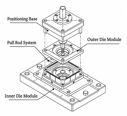
This fixture primarily consists of a positioning base, a tie-rod system, an outer stop disc module, and an inner stop disc module, as shown in Figure 1.
The positioning base is a high-strength cast iron or alloy steel component featuring precision-machined locating pin holes, a central boss, and chip grooves.
It is mounted to the machine tool spindle via a high-precision transition flange or a center-hole center;
During ultra-precision machining, a fixed center can be used to achieve a positioning accuracy of less than 1 μm.
The tie-rod system consists of several high-strength alloy steel tie rods; their lower ends are screwed into the tie-rod holes in the base, while their upper ends connect to the retaining discs.
The preload must be controlled to prevent crushing the workpiece.
The outer retaining disc module is a ring-shaped disc;
Its inner locking protrusions press against the outer end face of the sleeve and are locked in place via tie rods and nuts.
We machine the outer stop disc so its clamping surface stays parallel to the fixture base. We leave a small gap between its protrusions and the outer surface of the sleeve. This gap ensures the fixture only applies axial clamping force.
We use the inner stop disc module when we machine the outer circumference of the sleeve. A through-hole at its center fastens the module to the tie rods inside the base. Inner stop protrusions along its edge press against the end face of the sleeve’s inner bore.
This arrangement keeps the cutting tool path free from interference.
Design of Critical Dimensional Tolerances and Mechanical Properties
The design accuracy of a fixture is a prerequisite for its operational accuracy.
During the fixture design process, appropriate tolerance values should be specified for critical dimensions.
For example, the fit between the locating pin and the pin hole is an H7/p6 interference fit;
We control the tolerance of the distance between the locating base’s locating surface and the fixture rotation axis.
This surface sets the height of the locating sleeve. We limit this tolerance to 1/3–1/5 of the matching workpiece dimensional tolerance.
Take the workpiece dimension 1030–0.022 mm as an example; the fixture tolerance reaches roughly ±0.003 mm.
We apply the same rule to the side locating block. We restrict the tolerance of its distance to the fixture axis within 1/3–1/5 of the workpiece tolerance.
For the workpiece dimension 275 ± 0.04, the fixture tolerance is about ±0.013 mm. We adopt finite element analysis (FEA) to study the fixture from a mechanical standpoint.
We carry out static analysis and modal analysis on the fixture model. Static analysis calculates fixture deformation under peak cutting loads.
The total deformation must stay smaller than the defined positioning tolerance, such as 0.006 mm. Modal analysis identifies the fixture’s natural frequencies.
We keep these frequencies outside the excitation range of the machine spindle and common cutting forces.
This measure prevents resonant vibration. We strengthen long-arm cantilever structures, like support frames for large grinding machine fixtures.
Designers use oversized bolts to reinforce these joints. Engineers may also add counterweights for dynamic balancing.
This balancing step removes roundness errors triggered by rotational unbalance.
Experimental Validation and Comparative Analysis of Optimization Schemes
To validate the effectiveness of the aforementioned process and fixture optimization schemes, comparative experiments were designed and conducted.
Experimental Design
1. Test Specimens
This study selected bushings made of quenched and tempered 45 steel (hardness 250–280 HBW) as test specimens.
The inner diameter was specified as ϕ50H7 (+0.025/0), the outer diameter as ϕ65h6 (0/-0.019), and the coaxiality between the inner and outer diameters was specified as 0.01 mm.
2. Experimental Groups
Control Group: Utilized the traditional process sequence (rough turning of the outer diameter → rough boring of the inner diameter → finish turning of the outer diameter → finish boring of the inner diameter, totaling 4 setups) along with a standard three-jaw chuck and mandrel fixture;
Experimental Group: Utilized the optimized process sequence (on a turning-milling center, completing rough and finish machining of the outer diameter, end face, and inner diameter in a single setup) along with the innovative fixture designed in this study.
3. Testing Equipment
Coordinate measuring machine (CMM, accuracy 0.001 mm), roundness tester, and surface roughness tester.
4. Evaluation Criteria
Inner diameter dimensional error, outer diameter dimensional error, coaxiality between inner and outer diameters, wall thickness variation, machining time per part, and surface roughness Ra value.
Analysis of Results and Discussion
The inspection data from 30 parts processed in each group were averaged and compared; the results are shown in Table 1.
| Evaluation Indicator | Traditional Scheme (Control Group) | Optimized Scheme (Experimental Group) | Improvement |
|---|---|---|---|
| Inner Diameter Dimensional Deviation (mm) | ±0.018 | ±0.008 | Accuracy improved by 55.6% |
| Outer Diameter Dimensional Deviation (mm) | ±0.015 | ±0.006 | Accuracy improved by 60% |
| Concentricity (mm) | 0.018 | 0.007 | Accuracy improved by 61.1% |
| Wall Thickness Deviation (mm) | 0.045 | 0.022 | Uniformity improved by 51.1% |
| Single-Piece Processing Time (min) | 25 | 16 | Efficiency improved by 36% |
| Surface Roughness (Ra/μm) | 0.8 | 0.4 | Surface quality improved by 50% |
Table 1. Comparison of Processing Results Between Traditional and Optimized Schemes
As shown in Table 1, the performance metrics of the improved method are significantly better than those of the original method.
The improvement in machining accuracy is primarily due to the new fixture, which enables “single-positioning, sequential clamping,” thereby eliminating errors caused by repeated clamping.
Additionally, the adoption of a rational three-stage boring process and a PCD boring tool ensures dimensional stability;
The improvement in machining efficiency stems primarily from the consolidation of multiple operations and the application of multi-axis simultaneous machining, which significantly reduced setup time and machine downtime;
The substantial reduction in wall thickness variation clearly demonstrates that the clamping force distribution of this fixture is uniform, effectively preventing workpiece deformation—a factor of particular importance in the machining of thin-walled bushings.
Furthermore, SPC analysis of the experimental group’s mass production data revealed that the CPK value for bore diameter increased from 1.1 in the control group to 1.6, indicating a marked improvement in process capability and demonstrating the effectiveness of the error compensation and process control methods.
Conclusion
This study addressed key technical issues in the high-precision machining of bushings by developing a rational machining plan and optimizing a new type of specialized fixture.
Pilot production tests have verified that this approach is indeed feasible.
The conclusions are as follows: By adhering to the principles of rational process sequencing and centralized machining, implementing a three-stage precision boring process, and strictly controlling parameters and errors, machining quality and efficiency were improved;
A new “single-setup, sequential clamping” fixture structure was designed, enabling the machining of both the inner and outer circles of the sleeve in a single setup, which effectively reduced positioning errors and clamping deformation;
After optimization, the dimensional accuracy of key dimensions improved by over 55%, coaxiality was controlled within 0.007 mm, and efficiency increased by 36%, enabling stable high-volume machining.
In the future, we can develop intelligent adaptive fixtures integrated with micro-strain gauges, temperature sensors, and other components;
Explore lightweight fixture structures based on additive manufacturing;
And extend this process and design methodology to the machining of complex precision parts such as engine connecting rods and hydraulic valve bodies, thereby advancing the overall progress of precision manufacturing.