

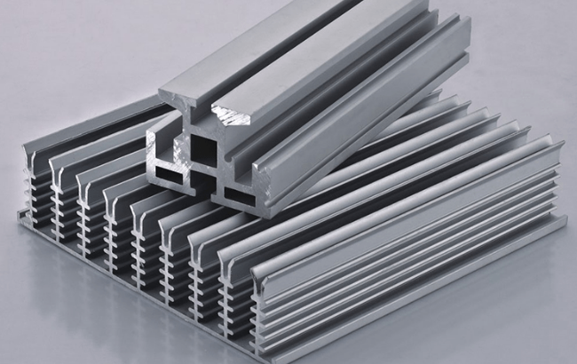
Aluminum alloy features light weight and outstanding corrosion resistance. These strengths make it a preferred lightweight material for rail vehicles.
It serves high-speed trains, metro trains and dedicated coal freight wagons in China. Railway manufacturers have adopted this material extensively across domestic rail transit systems.
To meet lightweighting requirements, a certain type of freight car utilizes aluminum alloy for components such as its side walls, roof, and underframe.
Since the underframe serves as the car’s bottom opening and closing structure and bears the weight of the cargo inside, the dimensions of its components and the quality of its welds are critical.
To establish a mature and reliable manufacturing process, this paper investigates the assembly and welding process for the underframe.
Structural Analysis
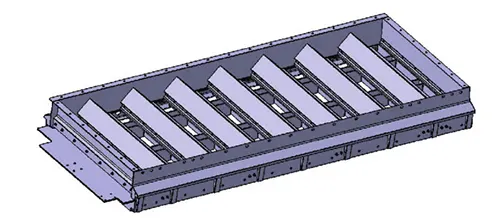
The bottom frame consists primarily of inner side frames, outer side frames, end frames, transverse ridges, vertical posts, crossbeams, and support panels.
The overall length is 2,500 mm, and the width is 1,069 mm. The structure is divided into two layers: the lower layer, where the crossbeams and support plates form the lower support framework;
And the upper layer, where the inner side frames, outer side frames, end frames, and transverse ridge form the main framework.
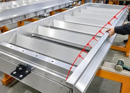
The structure is shown in Figure 1. Both the sheet metal and extruded profiles are made of EN AW6082-T6.
The bottom frame serves as the opening and closing mechanism for the bottom of the railcar’s cargo compartment.
A valve plate is installed between the support skeleton and the main frame to facilitate the unloading of grain cargo with a particle diameter of approximately 1 mm.
The top surface of the bottom frame must fit closely against the unloading opening on the railcar underframe.
A closed valve plate needs full bottom sealing to stop grain leakage. These functional requirements set strict limits for two geometric indicators.
The top surface of the bottom frame must meet flatness specifications. Engineers also control the gap between the upper and lower mating layers.
Technical specifications set strict acceptance criteria for welded assemblies. The bottom frame requires a top surface flatness below 2 mm. The diagonal deviation cannot exceed 2 mm.
Engineers restrict the straightness to 1 mm. The length tolerance stays within ±3 mm. The finished assembly must show no twist or distortion.
Aimultaneously, the clearance tolerance between the lower support skeleton and the upper main frame must be controlled within 0 to 0.7 mm.
Process Design
Process Design Objectives
The process design for the product is developed to ensure critical product dimensions while incorporating the principles of rapid component positioning and controllable weld quality.
First, the flatness of the bottom frame’s upper surface after welding must be within 2 mm to ensure proper alignment of the mounting surfaces.
Second, the clearance tolerance between the upper and lower structural layers after assembling the valve plate must be within 0 to 0.7 mm;
Third, given the large number of parts, assembly efficiency must be improved and error-proofing implemented;
Fourth, welding difficulty must be reduced, weldability improved, and distortion caused by welding avoided.
Modular Subassembly Welding Scheme
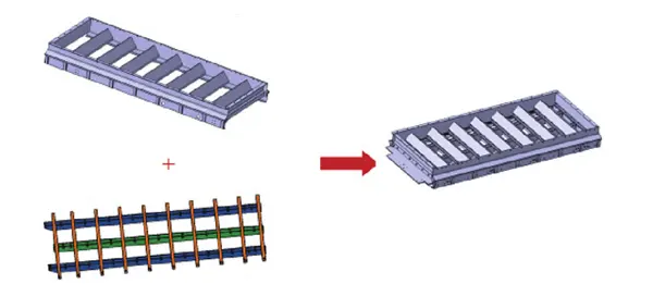
To ensure post-weld upper flatness and clearance tolerances, a split, modular welding approach is adopted, in which small subassemblies are welded first before final assembly, thereby reducing the accumulation of welding distortion.
First, the lower-layer crossbeams and support plates are welded together to form the support frame assembly, while the upper-layer side frames, end frames, and transverse ridges are welded together to form the upper frame assembly.
After sub-assembly welding, each assembly undergoes a preliminary adjustment to meet process dimensional requirements before final assembly welding is performed, as shown in Figure 2.
Hierarchical Tolerance Control Strategy
Designers need to guarantee gap tolerances between upper and lower structures and assembly clearances.
They analyze the whole structure and account for profile manufacturing tolerances and component machining tolerances. Process teams control tolerances for single parts and modular subassemblies.
They also manage assembly tolerances between these subassemblies. These controls define proper process dimensions.
Such measures secure the dimensional quality of the final product.
Mark-Free Positioning Fixture Design
To improve the assembly efficiency of mass-produced components, the fixtures are designed for mark-free positioning and assembly.
During the welding of the support frame, both the crossbeams and support plates are positioned using fixture mounting sockets;
During the welding of the upper frame, the side frames, end frames, and transverse ridges are similarly positioned using jig mounting seats;
When installing the columns, positioning templates are used to avoid the conventional process of first manually marking out and then manually positioning and assembling, thereby improving operational efficiency.
Welding Tooling and Deformation Suppression Measures
Workers gain better welding accessibility with customized tooling. All jigs adopt rotatable welding fixtures.
This design keeps welds in the PA or PF welding position. The setup lowers operational difficulty for welders.
The welding sequence follows a center-outward pattern. Welders use staggered skip welding toward both ends. This technique effectively suppresses welding deformation.
Manufacturing Process
Process Flow
The process flow for frame subassembly welding is shown in Figure 3. First, the support frame and upper frame are welded separately;
After welding, they are adjusted to meet requirements before the frames are assembled into a complete unit; finally, assembly and testing are performed.
Welding subassemblies separately before final assembly reduces the overall stress in the product and minimizes the accumulation of welding distortion.

Optimization of Weld Structure
1. Welds at the Transverse Ridge and Side Frames
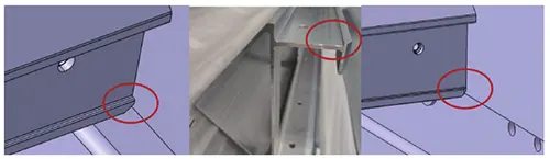
The transverse ridge features a protruding edge at the bend, which not only increases the wall thickness in that localized area—leading to poor weld fusion—but also hinders the welder’s smooth operation, thereby affecting the quality of the weld bead.
From a process perspective, grinding this area into a 55° bevel to avoid interference from the edge effectively ensures both the fusion quality and the bead quality of the weld, as shown in Figure 4.
2. Welds Between the End Frames and Side Frames
The upper welds between the end frames and side frames must be fully penetrated.
To ensure the quality of the weld fusion, a fillet weld backing pass process was implemented.
Process Design for Product Dimension Chains
Based on an analysis of the manufacturing process and product structure, the valve plate forms a sealed structure with the upper frame when closed, with a clearance tolerance requirement of (0 to +0.7) mm.
Since the structural design at this location involves dimensional fits between multiple components, a reasonable process dimensional chain must be designed.
The structure is shown in Figure 5.
Additionally, the width of the support frame must be aligned with that of the upper base frame, so the width dimensions of the components must be controlled.
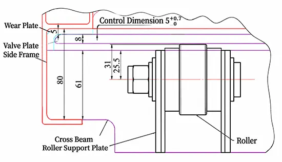
1. Design of Process Dimensions for the Valve Plate Installation Area in the Main Frame
(1) Tolerance Sources and Theoretical Dimensional Chain of the Assembly Gap
Many tolerance sources affect the gap between the valve plate and upper frame.
They cover thickness variations of the wear plate and valve plate, crossbeam height tolerance, bottom gate side-frame gap tolerance, and mounting-hole tolerances of the roller support plate.
The dimensional chain sets the crossbeam mounting height to 61 mm. Operators align the crossbeam flush against the top face of the roller support plate.
Mounting hole centers are positioned 25.5 mm below this reference surface. The roller diameter is 31 mm, the valve plate thickness is 8 mm, and the wear plate thickness is 5 mm.
Summing these values gives a total height of 79.5 mm. This reference design delivers the designed clearance of 0.5 mm.
(2) Tolerance Distribution and Risk Analysis
The wear plate tolerance is ±0.12 mm. The valve plate uses an 8 mm stainless steel sheet. GB/T 4237—2019 governs its thickness tolerance of ±0.35 mm.
The extruded crossbeam profile has a nominal height of 90 mm with ±0.5 mm tolerance.
Machining adds another ±0.1 mm tolerance to its mounting structure. The superposition yields a combined tolerance of ±0.6 mm.
The installation space for the bottom door lower crossbeam, covering inner and outer sides, is 80 mm ±0.8 mm. There is a 0.3 mm tolerance in the vertical direction for the mounting hole positions of the roller assembly.
Based on the above tolerances, it can be seen that the difference between the limit tolerance fit and the theoretical value can reach 2.17 mm.
If the mating dimensions of any component deviate toward the upper limit, assembly will be impossible;
If they deviate toward the lower limit, excessive gaps in the product will prevent the formation of a sealed structure.
(3) Optimized Component Dimensional Control Scheme
Therefore, the process dimensions of each component must be reasonably designed to ensure the final manufacturing dimensions of the product. Specifically:
① The valve plate is machined directly from sheet metal with a nominal thickness of 8 mm. The actual thickness must be determined based on the specific procurement batch;
The actual thickness of the procured sheet metal is approximately 7.8 mm. Determining the valve plate thickness reduces the number of control variables.
② The height of the lower section of the side frame is controlled by the profile die.
In the technical specifications for profile supply, the dimension (80 ± 0.8) mm is controlled to (80 ± 0.2) mm, with the reference dimension strictly controlled by the profile die.
③ The wear plate is either a machined part or a die-cast component; its thickness is controlled from (5 ±0.12) mm to 500.2 mm to prevent negative tolerances from causing assembly clearance.
④ The crossbeam height is (90 ± 0.5) mm. The design drawings for the crossbeam mounting notches specify a lower notch dimension of (29 ± 0.1) mm.
Profile height tolerances introduce variation during production. The roller support plate must sit flush with the crossbeam top face during assembly.
Manufacturers revise the dimensional control strategy for this crossbeam. They set its upper controlled dimension to 61 ± 0.1 mm.
⑤ Considering roller manufacturing tolerances and installation clearance, the locating dimensions of the mounting holes are executed according to the design negative tolerance;
The design dimensions are 25.5–0.1–0.4 mm, and the process control dimensions are 25.5–0. 55–0.65 mm, reducing the 0.5 mm clearance reserved in the design dimension.
⑥ The rollers use off-the-shelf bearings with high grinding precision; dimensional effects are not considered.
(4) Control Target after Optimization
Through process design of the dimensions of each component, the clearance tolerance after assembly is ensured to be within (0 to +0.7) mm, and to approach 0 mm.
2. Design of Process Dimensions for the Support Skeleton and Main Frame Width
Workers insert the support skeleton into the main frame during assembly. This operation requires qualified weld gaps between mating parts.
Designers control the width tolerances of both components. These tolerance limits guarantee a proper fit.
The support skeleton crossbeam and the lower part of the side frame are joined by a lap joint, while the vertical sections are joined by a butt joint.
During welding, the lap joints are welded first to ensure that the structural components fit tightly together. The internal width of the side frame is 1,069 mm, and the designed length of the crossbeam is (1,069 ± 0.2) mm.
To ensure proper assembly, the crossbeam width should be 2 to 3 mm narrower than the internal width of the side frame.
Taking into account a 1 mm contraction of the crossbeam and support plate after welding, the process-specified width of the crossbeam is designed as 1,069 – 0.5 – 1 mm.
Principles for Establishing Welding Parameters
The welding method used is gas metal arc welding (GMAW), with AWS A5.10 ER535 welding wire. Engineers conduct this work in accordance with standard EN 15614-2.
They gather fundamental data such as base material grade, plate thickness, joint configuration, and weld geometry.
Engineers select a qualified welding procedure qualification record based on these data. This record supports the compilation of the formal welding procedure specification.
Welding Distortion and Its Control
1. Welding Distortion
During the welding process, uneven heating causes the weld and its immediate vicinity to reach very high temperatures, while most of the surrounding metal remains unheated.
This prevents the metal in the weld and the near-weld zone from expanding and contracting freely.
Consequently, upon cooling, the weld undergoes varying degrees of contraction and develops internal stresses (both longitudinal and transverse), causing various types of deformation in the welded structure.
The bottom frame consists of multiple components, and the side frames feature multiple vertical welds distributed along their length, which can cause various types of welding distortion, as follows:
(1) Longitudinal Contraction Deformation
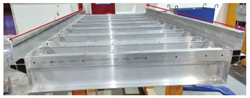
This primarily involves contraction deformation along the length of the upper frame. Transverse ribs and columns carry over ten welds along the side frame. These welds distribute continuously over the component length.
Post-weld measurements show longitudinal shrinkage of around 2 mm on the frame. A schematic diagram of the deformation is shown in Figure 6.
(2) Angular Deformation
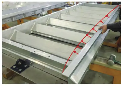
This deformation primarily occurs in the inner side frame. Operators perform tack welding for the upper frame assembly. The inner side frame features straight side members.
It shows low stiffness along the width direction. Transverse spine welds shrink after solidification.
This shrinkage pulls the inner frame inward. The inward bending reaches roughly 4 mm. Figure 7 illustrates this deformation pattern.
(3) Flexural Deformation
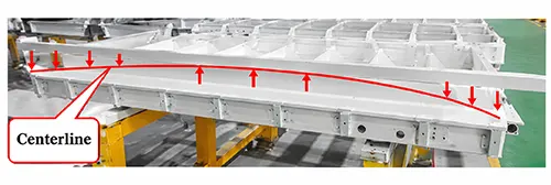
This deformation primarily occurs on the upper surfaces of the inner and outer side frames. Tack welds on transverse ribs form triangular weld arrangements for the upper frame assembly.
These welds push the middle sections of inner and outer side frames upward. The upward convex distortion creates around 4 mm flatness error. Final assembly adds welds between crossbeams and uprights on the bottom frame.
This welding step also produces upward bulging at the center of the inner and outer side frames. Figure 8 presents this deformation pattern.
2. Control of Welding Distortion
Common methods for controlling welding distortion are categorized into pre-welding prevention, in-process control, and post-welding correction.
Common pre-welding prevention methods include the counter-distortion method and the rigid clamping method; In-process control requires selecting appropriate welding procedures and sequences;
And common post-welding correction methods include mechanical straightening, heat treatment, and a combination of the two.
(1) Pre-welding Precautions
① Increase Length Allowance
Based on the 2 mm full-length shrinkage observed during prototype manufacturing, a length allowance of +1 to +2 mm was applied in the longitudinal direction both inside and outside the side frames.
After welding, the frame length tolerance is within 1 mm, which meets the requirements.
② Increase Rigid Clamping
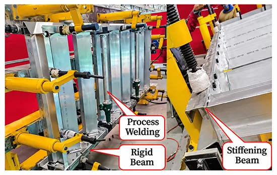
Since the inner side frame must be welded to the transverse ridge and end frames, anti-distortion measures cannot be implemented; the optimal control method is rigid clamping.
By adding rigid beams and width-wise process braces, the straight edges inside the side frame are rigidly clamped (Figure 9).
This controls the angular distortion in the longitudinal direction of the inner side frame within 1 mm after welding, thereby avoiding post-welding adjustments.
(2) Welding Process Control
① Tacking of the Upper Frame
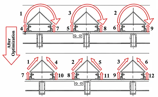
The welds on the transverse web are distributed in the middle of the side frames and form a triangular pattern, which significantly affects the warpage of the upper surface of the side frames.
Designers plan the welding sequence for transverse ribs carefully. They avoid localized heat accumulation on a single rib.
Heat concentration would trigger excessive deformation and stress concentration. Welders adopt intermittent, symmetrical, staggered and segmented welding.
Pilot production and validation support further optimization of this sequence. Engineers split the original continuous triangular weld into two separate welds.
This change cuts the concentrated heat input in this zone. It reduces angular distortion stress inside the side frame. Figure 10 illustrates this optimized welding scheme.
② Assembly and Welding of the Bottom Frame
During prototyping, the bottom frame was welded with the crossbeams and side frames under reverse deformation; the flatness after welding met the requirements.
The upright components were then welded in a free state.
Since the welds on the uprights run vertically along the lower part of the side frames, the contraction caused by welding at the bottom resulted in deflection of the upper surface.
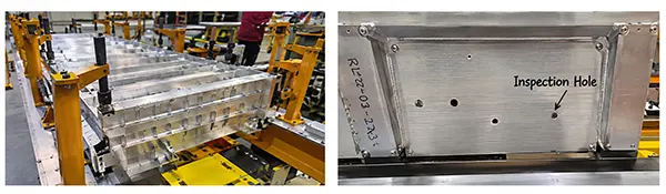
After optimization, the counter-deformation applied during the bottom frame assembly welding was increased from the original 4 mm to 6 mm.
Both the vertical members and crossbeams were welded under counter-deformation, and a staggered welding method was adopted.
As a result, the post-weld flatness met the requirement of no more than 2 mm.
The assembly welding and counter-deformation are shown in Figure 11.
(3) Post-Welding Straightening
Mechanical straightening involves selecting mechanical forces—such as hammering, pressing, or pulling—based on the structural shape, dimensions, and degree of distortion of the welded component to correct welding distortion.
This includes methods such as hammering, static pressure straightening, and weld seam rolling.
After the bottom frame was fully assembled, localized deformation caused by welding resulted in gap tolerances exceeding specifications.
Since the required adjustment was minimal, precise control was essential.
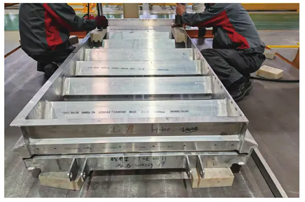
The use of the static pressure method for cold adjustment effectively prevented the reduction in strength and loss of control that can result from heat-based adjustments.
Nylon blocks are used as protective spacers between the hydraulic press ram and the product to prevent localized permanent deformation, as shown in Figure 12.
Using this adjustment method, the flatness of the clearance can be maintained within 0.5 mm, meeting the product’s design requirements.
Conclusion
Through a process study of the tack welding of aluminum alloy base frames, measures were implemented in both process design and welding techniques.
Through product prototyping and optimization, the product’s technical specifications were met, and process capability was established.
This provides a technical reference for the manufacturing processes of similar aluminum alloy structures.
(1) For parts with regular patterns and mass installation, using a marking-free positioning and installation method with jig alignment can improve product assembly efficiency and quality.
(2) When the weldability of a welded structure is poor, localized process optimization should be performed on the structure—such as using closed-bottom welding or beveling—to ensure the fusion quality of the welds and guarantee structural safety.
(3) Lengthwise shrinkage deformation of components can be effectively addressed using the length allowance method;
Angular deformation can be controlled by implementing rigid clamping measures tailored to the product’s structural characteristics.
(4) Deflection deformation can be comprehensively controlled through a combination of pre-deformation and segmented cross-welds.
(5) Post-weld deformation can be corrected with high precision using the static pressure method with cold adjustment.