




The development of advanced aerospace manufacturing has facilitated the widespread application of complex thin-walled structural components;
However, complex micro- and mini-thin-walled structural components are highly prone to deformation, instability, and vibration during the manufacturing process.
These issues severely limit the machining quality and product performance of such parts and have long been a focal point and challenge in research.
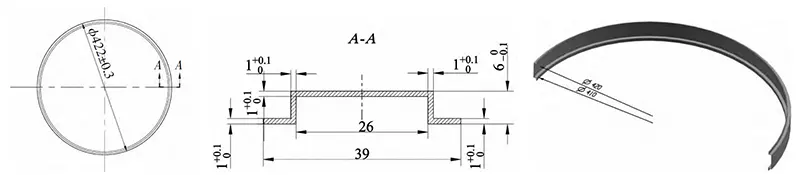
A certain thin-walled component features a channel skeleton with a wall thickness of 1 mm and a diameter of 422 mm, making it a typical long, thin-walled part.
Its structural shape is shown in Figure 1.
The material is a titanium alloy, grade TC4, with the following primary mechanical properties at room temperature: tensile strength σb ≥ 980 MPa and yield strength σs ≥ 830 MPa;
Researchers classify it as a difficult-to-machine material.
When machining this part, the low elastic modulus of the titanium alloy results in significant springback during cutting.
The tool’s rake face touches the workpiece over a large area.
This slows heat dissipation at the tool tip. Diffusion wear often develops in this region.
Rough turning makes the tool even more vulnerable to damage.
Machinists complete this thin-walled part in one machining operation.
They cannot use measuring tools such as outside micrometers or wall thickness calipers.
These tools cannot directly measure the wall thickness dimensions of 6–0.10 mm and 1+0.10 mm on the far side of the part.
When attempting to measure with a specialized wall thickness micrometer, it is difficult to position the part correctly;
Furthermore, the micrometer is too large to perform the measurement, which can easily result in dimensional inconsistencies between the two sides of the product.
Additionally, during machining, improper selection of machining methods or inadequate tool sharpening can easily lead to chatter marks at the 26 mm groove.
Countermeasures for Part Deformation and Vibration Marks During Machining
Analysis of Part Deformation and Vibration Marks During Machining
1. Analysis of Part Deformation During Machining
Manufacturers machine this thin-walled part from titanium alloy.
Titanium alloy delivers high specific strength and thermal strength, yet it has a low density (4.5 g/cm³), high hardness, poor thermal conductivity, and low elastic modulus.
The material’s high hardness requires greater cutting forces during machining, which generates significant cutting heat.
These high cutting forces can easily lead to substantial strain during machining, causing part deformation—a phenomenon that is particularly pronounced in the machining of thin-walled parts.
Meanwhile, poor thermal conductivity causes temperatures in the cutting zone to rise rapidly, further contributing to part deformation.
Machining continuously generates substantial cutting heat.
However, titanium alloys conduct heat poorly, so the material cannot easily dissipate this heat.
This raises cutting-zone temperatures rapidly and accelerates tool wear.
Insufficient tool sharpness results in uneven machining forces, which in turn leads to machining deformation.
Furthermore, the elastic modulus of titanium alloys (E = 110 GPa) is approximately half that of steel, making them more prone to deformation under external forces during machining.
In particular, under radial clamping forces, parts are more susceptible to elastic deformation, which increases the contact area between the machined surface and the tool’s rake face, thereby accelerating tool wear.
2. Analysis of the Causes of Vibration Marks
Titanium alloys have a low modulus of elasticity and low stiffness;
Therefore, during the machining of thin-walled parts, the workpiece undergoes elastic-plastic springback, causing significant vibration between the workpiece and the cutting tool.
This causes the turning tool to shift on the workpiece surface, resulting in ripples on the machined surface.
Researchers refer to these ripples as vibration marks.
A dull cutting tool can crush the titanium alloy, ultimately destabilizing the cutting process and creating vibration marks.
Additionally, titanium alloys inherently have low thermal conductivity and poor heat dissipation.
Therefore, if the cutting temperature becomes too high during machining, it can cause the titanium alloy to soften, thereby leading to the formation of vibration marks.
To prevent the formation of chatter marks during turning, it is necessary to select appropriate cutting tools, as well as cutting edge geometries and parameters, based on the characteristics of the titanium alloy.
Engineers can minimize chatter marks by optimizing machining parameters and effectively controlling cutting temperatures.
Countermeasures
1) Select carbide cutting tools or inserts that do not contain titanium (Ti).
The primary reason for choosing tools made of this material is that carbide exhibits good red hardness and excellent high-temperature wear resistance.
Machinists must select tools with no titanium content. Titanium inside the tool readily bonds with titanium from the workpiece material.
This bonding creates cold welding. It also worsens diffusion wear under high-temperature conditions.
Operators generally select YG, YH, and YW grades of cemented carbide; for machine-clamped inserts, they choose AlTiN and AlCrN HEPVD coatings.
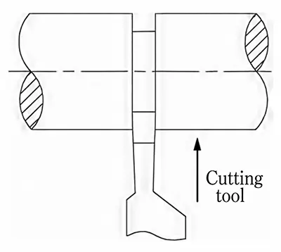
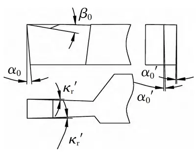
2) Based on the primary angles of the turning tool shown in Figures 2 and 3, this study focuses on analyzing the front angle β0, back angle α0, secondary back angle α0′, secondary rake angle κr′, and edge inclination angle λs during the machining process.
| Machining Type | Front Angle β₀ | Back Angle α₀ | Secondary Clearance Angle α₀′ | Secondary Cutting Edge Angle κᵣ′ | Cutting Edge Inclination Angle λₛ |
|---|---|---|---|---|---|
| Rough Machining | 3–5 | 1–3 | 1–3 | 1–2 | 0 |
| Finish Machining | 7–9 | 3–5 | 2–4 | 2–3 | 0 |
Table 1. Selection of Tool Cutting Parameters (°)
In this study, a parting tool was used for turning operations (as shown in Figure 2).
The machining quality and efficiency depend on the selection of the tool’s geometric parameters.
The parting tool primarily employs radial feed, with the cutting edge at the front serving as the primary cutting edge and the cutting edges on both sides serving as secondary cutting edges.
It is characterized by a narrow primary cutting edge, and a long tool body, resulting in relatively low tool strength.
Researchers use TC4 titanium alloy as the workpiece material in this study. This material has high hardness, strong toughness, and high ductility.
Therefore, to achieve better machining results, the tool’s geometric parameters must be selected appropriately, specifically: a. Selection of the rake angle β₀.
The rake angle directly affects cutting force, cutting temperature, and power.
Increasing the rake angle reduces cutting heat; however, if the rake angle is too large, it will reduce the heat transfer area and heat-storing volume, causing the cutting temperature to rise instead.
Operators adopt a smaller rake angle during rough machining to preserve tool life, while they may appropriately increase the rake angle for finish machining. b. Selection of the clearance angle α₀.
The clearance angle primarily affects the quality of the machined surface, tool life, and production efficiency.
Operators must ensure sufficient strength for the cutting edge during rough machining, so they select a smaller rake angle.
During finish machining, increasing the rake angle can extend tool life and improve the quality of the machined surface.
The material investigated in this paper has high hardness and high strength.
The workpiece is a large-diameter thin-walled part. It has weak structural stability and vibrates easily.
Machinists should reduce the rake angle appropriately during machining.
Selection of the secondary rake angle α0′.
The secondary rake angle primarily affects the quality of the machined surface and the sharpness of the cutting edge.
Based on multiple experiments, researchers select a secondary rake angle of 1° to 3° for rough machining to boost tool strength, and set the secondary rake angle to 2° to 4° for finish machining.
Keeping both secondary rake angles consistent ensures that the tool tip experiences balanced compressive stress during cutting, thereby reducing the likelihood of edge fracture. d.
For a parting tool, the primary rake angle κr is 90°, and the secondary rake angle κr′ is selected to be between 2° and 4°.
Machinists grind a roughly 0.2 mm radius on the primary cutting edge.
This step boosts cutting resistance. It stops resonance. Resonance happens when cutting vibrations match the machine tool’s natural frequency.
This resonance creates a shrill screeching noise. Figure 3’s front view shows this feature.
Selection of the rake angle λs. The rake angle refers to the angle between the primary cutting edge and the base plane.
If the tool tip is above the base plane, the rake angle is positive;
If the tool tip is below the base plane, it is negative; if the cutting edge is parallel to the base plane, the rake angle is 0°.
The rake angle primarily controls the direction of chip flow.
Given the characteristics of the material and structure being machined in this paper, a rake angle of 0° is selected.
3) During machining, the selection of the cutting fluid type is crucial, as it directly affects both tool life and production efficiency.
To enhance cooling efficiency, this paper uses cutting oils—which prioritize cooling while offering good lubricity and high thermal conductivity—and pressure-resistant emulsions to cool the workpiece.
This helps dissipate heat and prevents chip buildup near the cutting edge of the tool.
4) Keep the cutting tool sharp to ensure smooth chip evacuation and prevent chip adhesion and chipping of the cutting edge.
5) Since titanium alloys are prone to deformation during machining, the clamping force should not be set too high.
6) High-speed cutting generates a large amount of heat, causing rapid tool wear under high temperatures;
When machining titanium alloys, the machine tool spindle speed has the greatest impact on heat generation.
Researchers conducted machining tests on a titanium alloy tube.
The tube diameter reduces from 450 mm to 422.5 mm, and its length is 41 mm.
They set the feed rate at 0.15 mm/r and the depth of cut at 5 mm.
They ran the spindle at 80 r/min. The cutting edge suffers severe wear after three cutting passes.
Cutting resistance also rises sharply.
When using inserts of the same brand and adjusting the spindle speed to 50 r/min, severe wear on the cutting edge also occurred after machining six parts.
Ensuring Precision of Critical Dimensions
The conventional machining approach involves rough turning followed by finish turning using a finish turning tool.
However, the workpiece described in this paper features thin walls and a diameter exceeding 400 mm.
Operators use conventional machining methods for finish turning.
These methods easily chip the tool tip. They may also tear the workpiece. Severe chatter marks often appear on the part.
These defects stop the workpiece from meeting quality requirements.
Therefore, conventional machining processes are not suitable for such difficult-to-machine thin-walled parts.
Researchers need to further analyze the part’s characteristics to ensure the accuracy of critical dimensions.
Based on the part’s structural features, engineers optimized the original process flow.
As this is a thin-walled part, the main machining challenges include significant deformation, a high susceptibility to chatter marks, and an unreasonable original process sequence.
Additionally, machine tool aging and excessive overhang during machining contribute to part deformation and dimensional deviations, ultimately resulting in a product yield rate of only 82.8%.
Researchers analyzed problems that appeared during machining.
They identified three main causes of dimensional deviations.
First, unsuitable machining methods deform the part. Second, operators use inappropriate measurement approaches.
Third, the workpiece blank has inherent material characteristics.
The Impact of Improper Machining Method Selection on Dimensions
The selection of a machining method is critical; choosing an appropriate machining plan can effectively address the machining issues described above.
The solutions are as follows:
Engineers analyzed the drawing and machining challenges.
They decided the machining sequence. Operators first rough-turn the outer diameter with an external turning tool.
They machine it to 422.5 mm in diameter and L = 32.5 mm in length. This step removes the roughing allowance on the outer diameter.
Use a boring tool to rough-turn the L = 5 mm section to 4.93 mm (rough-turning the bore opening).
Use a grooving tool to machine the annular groove with a width of L = 26 mm down to L = 25.8 mm, leaving a 0.1 mm finishing allowance on each side.
This arrangement is primarily because the bore has not yet been rough-turned, and the grooved section has sufficient strength to prevent vibration marks caused by vibration.
Use a boring tool to remove the remaining stock from the hole again, ensuring the distance from the part’s end face to the bottom of the hole is L = 38 mm, leaving a finishing allowance of 1 mm on one side to ensure a tolerance of 6–0.1 mm during finishing.
Machine the other side using a custom-made internal grooving tool to ensure a wall thickness of 1 mm (since the outer diameter is L = 32.5 mm).
Operators turn the inner bore to L = 38 mm to secure sufficient strength and reduce the risk of damaging the tip of the internal grooving tool.
They maintain the finishing width at L = 36 mm and finish the outer diameter to 422.5 mm.
After turning is complete, stop the machine to take measurements.
Based on the measured values, adjust all tool offsets, then machine to the required dimensions in a single pass.
The Impact of Measurement Methods on Workpieces
Operators measure dimensions after precision turning. They must verify the part’s external dimensions.
These dimensions need to stay within tolerance limits. They also check all internal wall thicknesses. All wall thickness values must satisfy the requirements.
Since this part is machined in a single operation and has a large diameter, it cannot be measured directly using measuring tools such as an outside micrometer or a wall thickness caliper.
Instead, after cutting the wall thicknesses on one side to 6–0.10 mm and 1+0.10 mm, operators must use a specialized wall thickness micrometer for measurement.
The part has special structural features. These features make proper alignment difficult.
The wall thickness micrometer also has a short measuring range. Operators cannot take accurate readings with it.
Measurement errors occur easily. These errors create inconsistent actual dimensions on the two sides of the product.
To address this issue, operators can use a dial indicator (or lever gauge) to separately measure the symmetrical wall sections on the inner and outer sides of the part.
When operators move the tool holder longitudinally to the same position, they check whether the dial indicator needle stays at the same position or within the acceptable deviation range.
If the reading falls within the tolerance range, the part may be cut;
If it does not, fine-tune the wear on the precision turning tool and turn the part until the dimensions are consistent before cutting.
Using this method ensures that the dimensions of the inner and outer sides of the part remain consistent, thereby improving the first-pass pass rate of the part.
The Effect of Workpiece Blank Resting on Machining
The workpiece blank is a titanium alloy cylinder with an outer diameter of 450 mm, an inner diameter of 405 mm, and a length of 390 mm; its weight is approximately 15 kg.
Operators machine four finished products from one blank by using a three-jaw self-centering chuck with sector-shaped jaws for back support.
However, the back support force should not be excessive.
When machining the first two products, the blank protrudes too far from the chuck, shifting the center of gravity forward.
During prolonged machine downtime, the workpiece is prone to “sagging” under the force of gravity.
When operators restart the lathe for subsequent machining, they may observe slight runout in the previously machined sections.
To minimize the impact of the workpiece’s idle time on machining, the number of extended stoppages must be kept to a minimum when machining this product.
In particular, when the finishing allowance is minimal, operators must avoid prolonged stoppages, or even overnight machining.
Prolonged interruptions in machining can easily cause runout during finishing, thereby compromising the product’s machining quality.
Conclusion
This paper analyzes the material properties and machinability of titanium alloys.
The authors reviewed conventional part machining methods.
They considered three key factors. These factors include machining method selection, measurement method selection, and workpiece blank characteristics.
The authors optimized the machining process for thin-walled titanium alloy channel framework parts.
As a result, the first-pass pass rate was increased from 82.8% to 100%, significantly improving product quality.
The following main conclusions were drawn, which can serve as a reference for the future machining of large-diameter, thin-walled titanium alloy parts.
1) Titanium alloys have a low modulus of elasticity and exhibit significant springback during cutting;
Therefore, a smaller front angle or a larger back angle is generally used, and the tool tip should feature a rounded transition edge to enhance strength and prevent tip burning and chipping.
2) To minimize diffusion wear between the cutting tool and the workpiece, cutting tools with high hardness, good toughness, and little or no titanium (Ti) content should be selected for machining.
3) Researchers analyzed problems that arise during machining.
They identified three main causes of dimensional deviations in thin-walled titanium alloy parts.
Improper machining methods deform the part. Operators use unsuitable measurement techniques.
The inherent properties of the workpiece blank also affect machining.
4) Operators should minimize prolonged machine stoppages during machining to reduce the effect of gravity-induced sagging after the blank remains stationary for a long time.
They must avoid such stoppages particularly when the finishing allowance is small.