
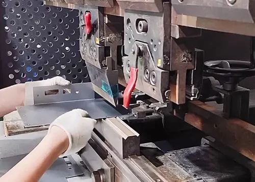





Bending is one of the most common forming methods in sheet metal fabrication. A CNC press brake uses dies to bend sheet metal to a specific angle.
While it may seem like a simple “press,” once you’re on the shop floor, you realize that achieving precise bends depends crucially on having reliable positioning references.
Bending Alignment: Having a Backgauge Isn’t Enough
On a CNC press brake, the backgauge serves as the primary alignment reference, but the part itself must also have an edge that can make contact with the backgauge.
In other words, for each bend to be accurate, there must be a stable, flat, and sufficiently long alignment reference adjacent to it.
This reference is not optional; it directly determines whether the sheet metal will wobble or shift after being placed in the die.
Risks of Missing a Valid Positioning Edge
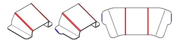
In the part shown on the left in Figure 1, the red bend edge hangs in the air with no effective positioning edge next to it.
When a part with this structure is placed on the machine, the sheet metal is prone to warping and slipping, resulting in unstable positioning.
The result is either an incorrect angle or dimensional deviations;
In severe cases, the part cannot be clamped at all, and the press brake simply cannot begin the bending process.
Design Optimization: Add a Dedicated Positioning Edge
This optimization solution in the middle is a classic example: adding a positioning edge (marked in blue) to the part so it can rest securely against the worktable and the backgauge.
The exploded view has also been included. It’s important to consider the feasibility of the bending process during the design phase—don’t wait until the drawings reach the shop floor to discover the job can’t be done.
Key Requirements for the Positioning Edge
One more thing: the positioning edge should ideally be a sufficiently long straight edge.
If it’s too short, it won’t provide reliable support; the backgauge won’t find a stable point of contact, and the part will still wobble.
Simply put, the locating edge acts as a “backing” for the press brake.
If this backing is unstable, a single positioning failure will affect every subsequent bend, naturally driving up the scrap rate.
With this modification, clamping becomes more stable, setup time is reduced, and the scrap rate goes down accordingly.
Spending an extra ten minutes on the drawing saves the shop two hours of trouble—it’s as simple as that.
Process Flanges: A “Temporary Lifeline” for Complex Parts
Some sheet metal parts have irregular shapes, with bent edges scattered here and there, making it impossible to find a reliable contact surface for conventional locating edges.
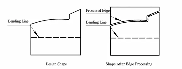
Take the part on the left in Figure 2, for example: its “designed shape” consists only of localized bend lines, and there isn’t a single straight edge on the sheet long enough to provide stable positioning.
In such cases, simply modifying the locating edges is no longer sufficient—you need to call in “external support.”
Limitations of Conventional Locating Edges for Irregular Sheet Metal
In such cases, consider adding a “process flange” to the exterior of the part as a temporary auxiliary structure.
A process flange is a section of material temporarily added outside the main body of the part.
It is used for positioning and clamping during processing; after all bending operations are complete, it is removed via laser cutting, punching, or milling.
Working Principle of the Process Flange
The image on the right in Figure 2, titled “Shape After Adding a Process Flange,” illustrates this approach: a small section is added on the outer side of the bend line.
This material does not contribute to the final product’s function; it exists solely to facilitate the manufacturing process.
Parts with multi-directional bends, irregular contours, or numerous internal cutouts are most prone to uneven stress distribution and tend to deform under pressure.
With a process margin added, the sheet metal is supported and clamped in certain areas during the bending process, significantly reducing the risk of deformation.
Trade-offs and Critical Notes for Process Flange Application
Of course, a process margin isn’t added for nothing.
It means an extra piece of material and an additional cutting step, which slightly increases both cost and scrap.
Therefore, the decision to add one requires careful consideration:
How complex is the part? What is the production volume?
For small batches with complex shapes, adding a process margin is often more cost-effective than repeated trial-and-error adjustments.
This technique is particularly common for precision sheet metal parts and mesh-type components.
However, one important reminder: When cutting away the process flange, pay close attention to the allowance and burrs.
Make sure not to cut into the main dimensions, and avoid leaving sharp edges that could cause injury during subsequent assembly.
The cut should ideally be located in an area that will be naturally concealed or inconspicuous later on, so as not to affect the appearance or functional surfaces.
Thorough Planning During the Drawing Phase
Thinking these matters through during the drawing phase will save the shop floor a lot of trouble.
Locating edges and process edges may seem like minor details in the bending process, but they actually directly determine whether a part can be formed consistently.
A well-designed locating edge improves both bending accuracy and efficiency;
When process edges are used correctly, many complex parts that were previously considered “unworkable” can be processed on a CNC press brake.
Early Collaborative Review Mechanism for Design and Process
In actual production, designers should consult with process engineers early in product development and incorporate bending feasibility into structural reviews.
Do not wait until the drawings are finalized to discover that a particular bend has no place for positioning.
During reviews, focus on the following core points: Is there a straight edge adjacent to each bend that can be used for positioning?
Is the positioning edge long enough? Do complex contours require process edges?
Process engineers, in turn, must professionally assess the part’s shape to judge whether standard positioning methods can be adopted.
If conventional positioning is not feasible, the process documentation must clearly specify detailed operational standards, including the adding position of process edges, the removal allowance of redundant materials, and the post-cutting processing requirements of parts.
Standardized Annotation of Bending Process Parameters
Key process information including the bending sequence, positioning methods, layout locations of process edges, and edge removal methods should be fully annotated on construction drawings or formal work instructions.
Standardized and detailed drawing annotations can effectively reduce the production floor’s dependence on the personal experience of senior technicians, avoid subjective guessing operations, and unify the processing standards of sheet metal bending.
Core Value of Front-End Process Optimization
Locating edges and process edges are not complicated structural designs, but the production cost caused by ignoring these details is extremely obvious.
Sufficiently optimizing positioning structures and verifying bending feasibility in the early drawing stage can fundamentally reduce workshop rework rates and material scrap rates.
This kind of front-end precise optimization is the most direct and cost-effective way to improve the overall production efficiency and yield of CNC press brake bending processes.
Conclusion
In CNC press brake bending, precision does not depend solely on machine accuracy or operator skill. The design of reliable positioning and process structures is equally important.
A properly designed locating edge provides stable contact with the backgauge, while a process flange offers temporary support when complex or irregular geometries cannot be positioned effectively through conventional methods.
These details may appear minor during the drawing stage, but they can have a significant impact on bending accuracy, setup time, deformation, rework, and material waste.
By evaluating bend feasibility early, selecting appropriate locating edges, and adding process flanges when necessary, designers and process engineers can prevent many problems before production begins.
Ultimately, good sheet metal design should consider not only what the final part looks like, but also how it will be manufactured.
Close collaboration between design and process teams, combined with clear annotations for bending sequences, positioning methods, and process-edge removal, can make CNC press brake operations more stable, repeatable, and cost-effective.