

China CNC Milling » Blog » CNC Precision Machining Process Optimization for 304 Stainless Steel Spray Arm Housing of Commercial Dishwashers
FAQ
What materials can you work with in CNC machining?
We work with a wide range of materials including aluminum, stainless steel, brass, copper, titanium, plastics (e.g., POM, ABS, PTFE), and specialty alloys. If you have specific material requirements, our team can advise the best option for your application.
What industries do you serve with your CNC machining services?
Our CNC machining services cater to a variety of industries including aerospace, automotive, medical, electronics, robotics, and industrial equipment manufacturing. We also support rapid prototyping and custom low-volume production.
What tolerances can you achieve with CNC machining?
We typically achieve tolerances of ±0.005 mm (±0.0002 inches) depending on the part geometry and material. For tighter tolerances, please provide detailed drawings or consult our engineering team.
What is your typical lead time for CNC machining projects?
Standard lead times range from 3 to 10 business days, depending on part complexity, quantity, and material availability. Expedited production is available upon request.
Can you provide custom CNC prototypes and low-volume production?
Can you provide custom CNC prototypes and low-volume production?
Hot Posts

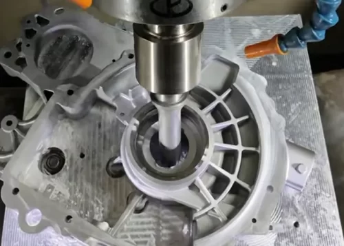
n the manufacturing of high-end commercial dishwashers, 304 stainless steel is commonly used for spray arm housings.
Although this material offers excellent corrosion resistance, toughness, and formability, it presents challenges during CNC precision machining, including high cutting forces, significant work hardening, and a tendency to form built-up edges.
These issues can easily lead to machining defects such as housing deformation, surface scratches, and dimensional deviations, which severely impact product yield rates.
Accordingly, this paper takes the 304 stainless steel spray arm housings used in high-end commercial dishwashers as its specific application focus.
Researchers systematically study its material properties and machining challenges.
They refine the cutting sequence and tool selection scheme.
With parameter optimization and experimental validation, they construct an efficient precision machining technology system for this type of metal housing.
This provides a theoretical basis and practical reference for the machining of similar precision stainless steel metal components.
Cutting Process Planning and Tool Selection Optimization
Cutting Process Sequence Planning
We adopt a staged machining sequence of “rough machining—semi-finishing—finishing” and optimize the operation sequence to minimize machining deformation and ensure dimensional accuracy.
The specific process sequence is as follows:
1. Blank Pre-treatment
Annealing of 304 stainless steel sheet metal (held at 850°C for 2 hours, followed by furnace cooling) to reduce material hardness and internal stress, and improve machinability;
2. Rough Machining
Use a face mill to mill the top and bottom surfaces, removing most of the excess material and leaving a 2 mm finishing allowance;
Use an end mill to machine deep cavities, stepped surfaces, and other features, leaving a 1 mm semi-finishing allowance;
Increase the feed rate and reduce the cutting speed during machining to improve roughing efficiency;
3. Semi-finishing
Remove the remaining allowance from roughing, leaving a 0.5 mm finishing allowance, correct deformation caused by roughing, and establish a foundation of precision for finishing;
4. Finishing
Operators adopt high-precision cutting tools for milling.
They machine flat surfaces, deep cavities and stepped surfaces. This guarantees dimensional accuracy and flatness.
They use taps to process threaded holes. They combine drills and reamers for through-hole machining.
This secures the precision and surface quality of the hole system.
5. Post-processing
Remove burrs from the workpiece surface and perform passivation treatment to enhance corrosion resistance.
Selection of Cutting Tool Materials
Given the machining characteristics of 304 stainless steel, operators should select cutting tool materials with high wear resistance, good thermal conductivity, and excellent anti-welding properties.
These materials must also meet the requirements of different machining processes.
The specific selection of cutting tool materials is shown in Table 1.
| Machining Operation | Tool Type | Recommended Material | Selection Criteria |
|---|---|---|---|
| Rough Milling of Flat Surfaces / Stepped Surfaces | Face Mill / End Mill | Cemented Carbide (WC-Co) + TiAlN Coating | High hardness (HRC 90–92), excellent wear resistance. TiAlN coating reduces adhesion-related wear and is suitable for high-speed cutting. |
| Finish Milling of Flat Surfaces / Deep Cavities | High-Precision Face Mill / End Mill | PCD (Polycrystalline Diamond) Tools | Extremely high hardness (HV 8000–10000), excellent wear resistance, and smooth cutting surfaces. Effectively suppresses built-up edge formation and ensures surface roughness Ra ≤ 0.8 μm. |
| Drilling | Twist Drill | Cemented Carbide + TiN Coating | Good rigidity and high impact resistance. TiN coating improves lubricity and reduces adhesion and wear during drilling. |
| Reaming | Carbide Reamer | Ultrafine-Grain Cemented Carbide | High dimensional accuracy and excellent wear resistance, ensuring hole tolerance of ±0.02 mm. |
| Thread Machining | Tap | High-Speed Steel (HSS-E) + TiN Coating | Good toughness and strong resistance to chipping. TiN coating improves cutting smoothness and prevents thread adhesion and galling. |
Table 1. Tool Materials and Selection Criteria for Different Machining Operations
Optimization of Cutting Tool Geometric Parameters
Cutting tool geometric parameters directly affect cutting force, cutting temperature, built-up edge formation, and surface quality.
Taking into account the machining characteristics of 304 stainless steel, we optimized the geometric parameters of key machining tools (face mills, end mills, and drills).
The specific optimized parameters are shown in Table 2.
| Tool Type | Key Geometric Parameters | Optimized Parameter Values | Optimization Objectives |
|---|---|---|---|
| Face Mill (Finish Machining) | Rake Angle, Clearance Angle, Cutting Edge Radius | Rake Angle γ₀ = 12°; Clearance Angle α₀ = 15°; Cutting Edge Radius rₙ = 0.2 mm | Reduce cutting forces, suppress built-up edge formation, improve surface quality, and prevent cutting edge chipping. |
| End Mill (Deep Cavity Machining) | Helix Angle, Number of Flutes, Length-to-Diameter Ratio | Helix Angle β = 45°; Number of Flutes z = 4; Length-to-Diameter Ratio L/D = 3:1 | Improve tool rigidity, reduce vibration, enhance chip evacuation, and minimize machining deformation. |
| Twist Drill (Drilling) | Point Angle, Chisel Edge Inclination Angle, Flute Width | Point Angle 2φ = 118°; Chisel Edge Inclination Angle ψ = 55°; Flute Width bₙ = 2.5 mm | Reduce drilling resistance, improve centering accuracy, enhance chip evacuation, and lower cutting temperature. |
Table 2. Optimization Analysis of Tool Geometry Parameters
Optimization of Cutting Parameters
Cutting parameters (cutting speed vc, feed rate f, and depth of cut ap) are key factors affecting machining quality, machining efficiency, and tool life.
This paper focuses on the face milling process during the finishing stage. Researchers adopt orthogonal experimental design (OED).
They use it to optimize cutting parameters. They choose three evaluation indicators.
These indicators include surface roughness Ra, dimensional error Δd and material removal rate Q.
Material removal rate Q reflects machining efficiency. This method helps researchers find the optimal combination of cutting parameters.
Experimental Design
1. Experimental Equipment: CNC vertical machining center (Model: VMC850), Vickers hardness tester (HV-1000), surface roughness meter (TR200), coordinate measuring machine (PH10T);
2. Test Material: 304 stainless steel frame housing specimen (450 mm × 320 mm × 80 mm);
3. Cutting Tool: PCD face milling cutter (diameter φ100 mm, number of teeth z = 4, front angle 12°, back angle 15°); 4.3.
Orthogonal Experimental Factors and Levels:
We selected cutting speed vc, feed rate f, and depth of cut ap as experimental factors and set three levels for each factor.
The experimental factors and levels are shown in Table 3;
4. Experimental Design: An L9(34) orthogonal experimental design was adopted, consisting of 9 experimental groups, each repeated 3 times.
The average value was taken as the evaluation result.
| Level | Cutting Speed, vc (m/min) | Feed Rate, f (mm/rev) | Depth of Cut, ap (mm) |
|---|---|---|---|
| 1 | 150 | 0.10 | 0.3 |
| 2 | 200 | 0.15 | 0.4 |
| 3 | 250 | 0.20 | 0.5 |
Table 3. Orthogonal Experimental Factors and Levels
Test Results and Analysis
We conducted machining tests following an orthogonal experimental design and measured surface roughness Ra, dimensional error Δd, and material removal rate Q for each test group.
The test results are shown in Table 4 below.
The formula for calculating the material removal rate Q is: Q = vc × f × ap × z × 10⁻³ (cm³/min), where z is the number of cutting teeth.
We used range analysis and analysis of variance to determine how significantly each cutting parameter affects the evaluation indicators:
1.Factors Affecting Surface Roughness Ra
Cutting speed vc has the greatest influence (contributing 42.3% of the variance), followed by feed rate f (contributing 35.6% of the variance), while depth of cut ap has the least influence (contributing 22.1% of the variance);
As the cutting speed increases, Ra first decreases and then increases; as the feed rate increases, Ra rises significantly;
2. Effects on Dimensional Error Δd
Cutting speed vc has the greatest influence (48.7% contribution to variance), followed by depth of cut ap (31.2% contribution to variance), while feed rate f has the least influence (20.1% contribution to variance);
At a cutting speed of 200 m/min, dimensional error is minimal; excessive depth of cut (ap) tends to cause deformation, leading to increased dimensional error;
3. Effects on Material Removal Rate (Q)
The depth of cut (ap) has the greatest influence (variance contribution rate of 51.5%), followed by the feed rate (f) (variance contribution rate of 32.8%), while the cutting speed (vc) has the least influence (variance contribution rate of 15.7%);
As the depth of cut and feed rate increase, Q improves significantly.
| Experiment No. | Cutting Speed, vc (m/min) | Feed Rate, f (mm/rev) | Depth of Cut, ap (mm) | Surface Roughness, Ra (μm) | Dimensional Deviation, Δd (mm) | Material Removal Rate, Q (cm³/min) |
|---|---|---|---|---|---|---|
| 1 | 150 | 0.10 | 0.3 | 1.25 | 0.032 | 18.0 |
| 2 | 150 | 0.15 | 0.4 | 1.52 | 0.028 | 36.0 |
| 3 | 150 | 0.20 | 0.5 | 1.88 | 0.035 | 60.0 |
| 4 | 200 | 0.10 | 0.4 | 0.78 | 0.018 | 32.0 |
| 5 | 200 | 0.15 | 0.5 | 1.05 | 0.022 | 60.0 |
| 6 | 200 | 0.20 | 0.3 | 1.32 | 0.025 | 48.0 |
| 7 | 250 | 0.10 | 0.5 | 0.92 | 0.020 | 50.0 |
| 8 | 250 | 0.15 | 0.3 | 1.18 | 0.024 | 45.0 |
| 9 | 250 | 0.20 | 0.4 | 1.45 | 0.029 | 80.0 |
Table 4. Analysis of Orthogonal Experimental Results
We considered both machining quality (Ra ≤ 0.8 μm, Δd ≤ ±0.02 mm) and machining efficiency and identified the optimal cutting parameter combination: vc = 200 m/min, f = 0.10 mm/r, and ap = 0.4 mm.
Under this combination of parameters, the surface roughness is Ra = 0.78 μm, the dimensional error is Δd = 0.018 mm, and the material removal rate is Q = 32.0 cm³/min, thereby simultaneously meeting both precision and efficiency requirements.
Test Validation and Effect Analysis
Validation Test Plan
We selected three 304 stainless steel frame housing specimens for high-end commercial dishwashers to verify the feasibility of the optimized cutting process, tool selection, and cutting parameters.
We carried out machining tests following the optimized process sequence (pretreatment → rough machining → semi-finishing → finishing → post-treatment), the tool selection scheme (Table 2), and the optimal cutting parameters (vc = 200 m/min, f = 0.10 mm/r, ap = 0.4 mm).
Additionally, we selected three test specimens machined by conventional methods (standard cutting tools + empirical parameters) as a control group to compare machining quality and efficiency between the two groups.
Verification Results and Analysis
The comparison of machining quality and efficiency between the two groups of test specimens is shown in Table 5 below, where machining efficiency is expressed as the time required to finish-machine a single shell.
Experimental Group | Surface Roughness, Ra (μm) | Dimensional Deviation, Δd (mm) | Flatness (mm) | Finish Machining Time (min) | Qualification Rate (%) |
|---|---|---|---|---|---|
Optimized Group (Proposed Method) | 0.72–0.78 | 0.015–0.018 | 0.010–0.013 | 45 | 100 |
Control Group (Conventional Process) | 1.35–1.62 | 0.028–0.035 | 0.020–0.025 | 68 | 66.7 |
Table 5. Comparison of Machining Quality and Efficiency Between Two Experimental Groups
As shown in Table 5, the optimized machining process offers the following significant advantages over the traditional process.
1.) Machining quality has improved significantly: Surface roughness (Ra) was reduced by more than 45.5%, dimensional errors were reduced by more than 38.6%, and flatness improved by more than 40.0%, all of which meet design requirements;
2.) Machining efficiency has increased significantly: The time required for the finish machining of a single housing was reduced by 33.8%, effectively improving production efficiency;
3.) Product yield rate has significantly improved: The optimized group achieved a 100% yield rate, far exceeding the control group’s 66.7%, thereby reducing production costs.
Furthermore, observation of tool wear revealed that the optimized tool selection scheme extended tool life by more than twofold, further reducing production consumable costs.
Conclusion
This paper takes the 304 stainless steel spray arm housing for high-end commercial dishwashers as its application case.
This work focuses on cutting procedures and tool selection for metal housings in CNC precision machining. It follows a clear logical framework.
The framework covers material properties, processing difficulties, tool selection, parameter optimization and experimental verification.
Researchers build a CNC machining technical framework for precision stainless steel metal housings.
It offers dependable technical references. Manufacturers use it to produce high-end commercial dishwashers and similar precision stainless steel parts.
Future research may extend the scope. Researchers will study metal housings made from multiple materials such as 316 stainless steel and titanium alloys.
They will also explore parts with complex structures. Engineers integrate smart manufacturing technologies.
They realize intelligent optimization for machining processes and tool selection.
This promotes high-quality development of the high-end equipment manufacturing industry.