
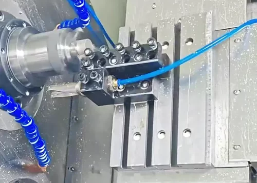





When machining produces continuous ribbon-like chips, not only does this make it easy to scratch the machined surface of the workpiece and damage the cutting edge, but in severe cases, it can also pose a threat to the operator’s safety.
Therefore, taking necessary process measures to control chip formation and breakage has always been an extremely important technical issue in the machining industry.
Since chips are the result of deformation in the chip layer, altering cutting conditions is an effective way to change chip characteristics and achieve chip breaking.
Factors influencing cutting conditions primarily include workpiece material, tool geometry, and cutting parameters.
In general, chips must meet the following basic conditions:
Chips must not become entangled on the cutting tool, workpiece, or adjacent tools and equipment;
Chips must not fly off to ensure the safety of operators and observers;
During finishing operations, chips must not scratch the machined surface of the workpiece, thereby affecting the quality of the machined surface;
The tool must maintain its intended service life by preventing premature wear and minimizing tool breakage.
As the tool discharges chips, the chips must not obstruct the coolant flow or scratch the machine tool ways or other components.
Classification of Chip Shapes
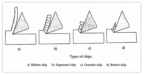
Different degrees of plastic deformation produce different types of chips, as shown in Figure 1.
When machining ductile materials, the cutting process primarily produces ribbon-like, segmented, or granular chips.
When machining brittle materials, the cutting process generally produces fragmented chips.
Ribbon Chips
Ribbon chips are continuous chips with a smooth underside and a fuzzy upper surface, as shown in Figure 1-1a.
These chips tend to form when machining ductile metals at high cutting speeds with tools having large front angles.
They result from insufficient deformation of the cut layer.
Although the cutting process remains smooth and produces a workpiece with low surface roughness when it generates ribbon chips, the chips do not break easily.
The continuous chips often tangle, scratch the workpiece, and even interfere with the machining process.
Therefore, engineers must not overlook the issue of chip breaking.
Segmented Chips
Segmented chips are chips with a smooth underside and distinct, deep cracks on the back, as shown in Figure 1-1b.
This type of chip tends to form when machining ductile materials at low cutting speeds with a tool having a reduced rake angle.
It results from extensive deformation of the chip layer, which has reached the point of shear fracture.
When the cutting process produces segmented chips, it becomes unstable and generates a relatively high workpiece surface roughness.
Granular Chips
Granular chips are uniform, granular-shaped chips, as shown in Figure 1-1c.
Machining ductile metals at very low cutting speeds with tools that have a small rake angle commonly produces this type of chip.
Extensive deformation of the cut layer causes the material to reach its shear failure limit, which fractures the chip along its thickness.
When the cutting process produces granular chips, it becomes unstable and generates a higher workpiece surface roughness.
Shattered Chips
Shattered chips are irregular, fine-grained chips, as shown in Figure 1-1d.
Cutting brittle materials forms these chips because the cutting layer undergoes elastic deformation and then suddenly fractures with almost no plastic deformation.
When the cutting process produces shattered chips, it becomes unstable, subjects the cutting edge to significant impact forces, and generates a rough and uneven machined surface.
As can be seen from the above, the type of chip varies depending on the workpiece material and cutting conditions.
Therefore, during the machining process, one can determine whether the cutting conditions are appropriate by observing the chip morphology, and one can also adjust the cutting conditions to alter the chip morphology, thereby optimizing it for more efficient production.
The Principle of Chip Breakage
During metal cutting, the chip’s deformation directly determines whether it breaks easily.
Therefore, studying the principle of chip breakage must begin with an examination of the laws governing chip deformation.
The chips formed during the cutting process undergo significant plastic deformation, which increases their hardness while significantly reducing their plasticity and toughness.
This phenomenon is known as work hardening.
After work hardening, the chips become hard and brittle, making them prone to breaking when subjected to alternating bending or impact loads.
The greater the plastic deformation the chip undergoes, the more pronounced the hardening and brittleness become, and the easier it is for the chip to break.
When machining high-strength, high-plasticity, and high-toughness materials that are difficult to break, efforts should be made to increase the deformation of the chip in order to reduce its plasticity and toughness, thereby facilitating chip breaking.
Two components constitute chip deformation.
Basic Deformation
The first component is formed during the cutting process; we refer to this as basic deformation.
Chip deformation measured during free cutting with a flat-faced turning tool is relatively close to the value of basic deformation.
The main factors affecting basic deformation are the tool rake angle, negative chamfer, and cutting speed.
The smaller the rake angle, the wider the negative chamfer, and the lower the cutting speed, the greater the chip deformation—which is more conducive to chip breaking.
Therefore, reducing the rake angle, widening the negative chamfer, and lowering the cutting speed can serve as measures to promote chip breaking.
Additional Deformation
The second component is the deformation the chip undergoes during flow and curling, which we refer to as additional deformation.
This is because, in most cases, the basic deformation during the cutting process alone is insufficient to break the chip;
The cutting process must apply additional deformation to achieve hardening and chip breakage.
The simplest method to induce additional deformation in the chip is to grind (or press) a chip-breaking groove of a specific shape into the front face of the tool, forcing the chip to curl and deform as it flows into the groove.
After undergoing this additional curling deformation, the chip becomes further hardened and embrittled;
When it collides with the workpiece or the rear face of the tool, it breaks easily.
Chip-Breaking Methods
The fundamental cause of chip breakage or continuity lies in the deformation and stress generated during chip formation.
When the chip is in an unstable state of deformation or the stress reaches its strength limit, the chip breaks; typically, the chip curls and then snaps.
Common chip-breaking methods include the proper selection of tool geometry angles, cutting parameters, and the grinding of chip-breaking grooves.
Reducing the Front Angle and Increasing the Main Rake Angle
The rake angle and main rake angle are tool geometric angles that significantly influence chip breaking.
Reducing the rake angle intensifies chip deformation, making it easier for the chip to break.
However, since reducing the rake angle increases cutting force, it limits the ability to increase cutting parameters;
In severe cases, it can damage the tool or even cause the machine to stall.
Therefore, reducing the rake angle alone is generally not used as a standalone method for chip breaking.
Increasing the rake angle increases the cutting depth, facilitating chip breaking.
For example, under the same conditions, a 90° tool breaks chips more easily than a 45° tool.
Additionally, increasing the rake angle helps reduce vibration during machining.
Therefore, increasing the rake angle is a proven and effective method for chip breaking.
Reducing Cutting Speed and Increasing Feed Rate
Adjusting cutting parameters is another measure for chip breaking.
Increasing the cutting speed softens the base metal of the chip and prevents sufficient deformation of the chip, which hinders chip breaking;
Conversely, reducing the cutting speed facilitates chip breaking.
Therefore, during turning, the operator can achieve chip breaking by lowering the spindle speed to reduce the cutting speed.
Increasing the feed rate increases the cutting depth, making chip breaking easier.
This is a commonly used chip-breaking method in machining;
However, increasing the feed rate significantly increases the surface roughness of the workpiece.
Machining Chip-Breaking Grooves
Chip-breaking grooves refer to grooves machined into the tool’s rake face.
The shape, width, and angle of the chip-breaking grooves are all factors that influence chip breaking.
1. Shape of the Chip-Breaking Groove
There are three commonly used types of chip-breaking grooves: broken-line, straight-line-arc, and full-arc, as shown in Figure 2.
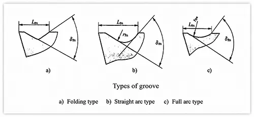
When machining carbon steel, alloy steel, and tool steel, you can choose between zigzag, straight-line-arc, and chip-breaking grooves;
When machining workpieces made of highly ductile materials, such as pure copper or stainless steel, you can choose a full-arc chip-breaking groove.
2. Chip-breaking Groove Width
The width of the chip-breaking groove has a significant impact on chip breaking.
Generally speaking, the narrower the groove width, the smaller the curl radius of the chip, the greater the bending stress on the chip, and the easier it is for the chip to break.
Therefore, using a narrower chip-breaking groove width is beneficial for chip breaking.
However, designers must determine the width of the chip-breaking groove in conjunction with the feed rate and cutting depth (a_p).
When the chip-breaking groove width matches the feed rate, the cutting process can form a C-shaped chip.
However, if the chip-breaking groove is too narrow, chip jamming is likely to occur, increasing the load on the turning tool and potentially damaging the cutting edge.
Conversely, if the chip-breaking groove is too wide, the curling radius of the chip becomes too large, resulting in insufficient deformation of the chip and making it difficult to break.
As a result, the chip often fails to flow along the bottom of the groove and forms an unbroken ribbon-like chip.
The width of the chip groove should also be appropriate for the depth of cut;
Otherwise, if the groove is too narrow, the chip appears wide and does not curl easily within the groove, often failing to flow along the bottom and forming a ribbon-like chip.
If the groove is too wide, the chip appears narrow, flows more freely, does not deform sufficiently, and also fails to break.
To achieve satisfactory chip-breaking results, the operator should select an appropriate chip-breaking groove width based on the specific machining conditions.
For workpiece materials with lower hardness, the groove should be narrower; conversely, for harder materials, the groove should be wider.