


As we all know, the traditional processing method of knurling is to install knurling knives on the CNC machine tool lathe to perform the extrusion process or use the knurling tool to roll.
And for the following cases and then use the original processing method is difficult to meet the design requirements.
- (1) Knurling parts for slender shaft parts.
- (2 ) There are more than two forms of knurling requirements on the same part (straight plus mesh or different modulus).
- (3 ) Knurling part shape and position tolerance requirements are relatively high.
- (4 ) Knurling parts in the parts of the end face or hole wall.
- (5) Complex structure of the parts and so on.
In addition, due to the structure of the CNC machine tool is a high-precision level, excessive external forces are likely to cause a reduction in the accuracy of the machine tool or even damage.
According to years of experience in processing, combined with CNC machine tools, multi-thread interpolation function and spindle locking function developed a new knurling processing method.
The use of macro program function to prepare the processing program, can be very convenient to process various forms of knurling.
We can combine various functions of the CNC machine tool to carry out several typical processing methods.
The following sections introduce these methods in detail.
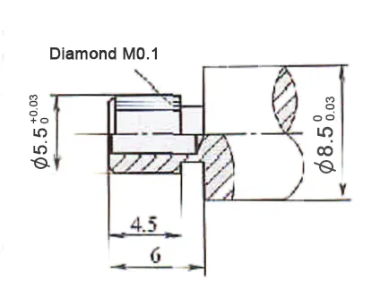
Multi-head thread turning function diamond knurling
The principle of this process is to see the diamond as positive and negative staggered multi-head thread.
Take the parts in Figure 1 as an example.
The traditional machining process for the first car system involves several steps.
First, operators complete all processes except for knurling and the φ1.6 mm holes.
Next, a rolling tool is used to roll the diamond knurling.
Finally, the φ1.5 mm holes are machined.
Due to the knurling at the shape and position tolerance requirements are relatively high, and the second clamping caused a long period of time, the scrap rate is high.
After the change to a new machining process, because all the steps of the part is a clamping completed, so the machining accuracy is easy to ensure.
The specific macro program is as follows.
CNC longitudinal cutting automatic lathe (center-facing) multi-threaded instruction format.
G32IP – F – Q -; (I P -: end point, F -: pitch in the long axis direction, Q -: thread start angle)
...

N 4:

T0404 M03 S200;                         set tool No.4, spindle rotate positively

G0X5.Z -2.;                             to start of cycle

#1=0;                                    set thread angle start point

WHILE[#1LT360000]DO1;                   set cycle condition

G0X2.85;                                 enter coordinate start point

G32Z5.5 F12.Q#1;                         turn thread

X5.

G0Z - 2.;                                return to cycle start point

#1=[#1+24000];                           Set the next thread angle start point

END1 ;

T 0; Cancel the tool patch

M05;

T0404 M04 S200;                          Turn the following left-hand thread

G0X5. Z- 2.

#1=0;

WHILE[#1LT360000]DO1;

G0X2.85;

G32Z5.5 F12. Q#1;

X5.

G0Z-2.

#1=[#1+24000];

END1 ;

T 0;

M05;

...
Utilizing the phenomenon of messy buckling to diamond knurling
The phenomenon of buckling is common during thread turning.
This feature can also be used to create diamond knurling.
Note: This method is more suitable for parts that have a small number of thread starts and a small helix angle.
But can increase the spindle speed, application also depends on the specific circumstances, this paper aims to introduce a method.
Figure 1 parts, the program is as follows.
N4:

T0404 M03 S1200;                  adjust the No. 4 knife; spindle rotation

G0X5. Z- 2.;                      set the cycle start point

#1=-2.;                            sets start of feed (Z-axis)

#2= -14.;                          Setting the end point of tool feed (Z-axis)

WHILE[#1GE#2]DO1;                  Setting the cycle condition

G32X2.85 Z5.5 F12.;                Turning thread

G0X5.

#1=[#1-1.];                        Set the start point of the next feed

G0Z#1;

X2.85

END1 ;

G0X20.;

T 0;

M05;

T0404 M04 S1200;                     following turning left-hand thread

G0X5. Z- 2.

Z- 2.; #1=-2.

#2= -14.;

WHILE[#1GE#2]DO1;

G32X2.85 Z5.5 F12.;

G0X5.

#1=[#1-1.];

G0Z#1;

X2.85;

END1 ;

G0X20.;

T 0;

M05;

...
Turning straight knurling with the spindle lock function
The principle behind this method involves locking the spindle.
Operators prefer a smaller index value because it allows for more accurate indexing.
The machine pulls out a longitudinal groove on the part surface during machining.
The continuous grooves form a straight-pattern knurling.
Such as Figure 2 parts, the program is as follows:
...

N5;

M50;                     spindle lock

T0606 G0X5.2 Z-2.;      set the starting point

#1=0;

WHILE[#1 LT 359.]DO1;    Set cycle conditions

G0 C#1;                  Angle starting point

G01 G98 Z5. F300;        Feed

U0.5; Return

G0 Z -2.

X5.2

#1=[#1+12.];             Set the next angle

END1

G0X20. Z-1.

M51                       Spindle Lock Release

T0                        Cancel Tool Patch

...
Note
If the thread rise angle is large, operators can increase the back angle appropriately.
They can then use one tool to process both the left and right rotary patterns.
If the thread rise angle is too small, use two cutters or one cutter with double tips to find the correctness in two patches.
The back angle is normal to the back angle, and the tip angle is equal to the angle of the pattern teeth.
Since the entire process involves intermittent cutting, operators should select tools made from high-strength, impact-resistant materials. (See Figure 3.)
Conclusion
This machining process development suits small-batch, multi-species production modes well.
When combined with increasingly mature group technology, it can greatly improve product quality.
At the same time, it helps reduce development costs.