


With the trend toward miniaturization in the market, high-precision core holes with diameters of φ0.4 or smaller are becoming increasingly common in molds.
In recent years, there has been a significant increase in the number of molds featuring core holes with diameters of φ0.4 or smaller, with tolerance requirements for these holes typically around 0.005 mm. The diameter and cylindricity of these holes are subject to extremely stringent specifications.
Traditionally, the primary methods for machining such small holes in mold steel include CNC machining, EDM (Electrical Discharge Machining), drilling machines for pilot holes, and slow-speed wire cutting.
Previously, all holes with diameters of φ0.5 or larger were machined using these three methods, which were sufficient for such applications. The specific method chosen depends on the product structure.
However, holes with diameters of φ0.4 or smaller have never been processed before, especially the recently frequent φ0.35+0.005 +0.001 and φ0.32+0.005 +0.001 holes.
Using the previous processing methods often resulted in issues such as excessive hole diameter and poor cylindricity, making the processing of such holes a bottleneck in mold manufacturing.
Process Analysis of the Part
· Process Requirements for the Part
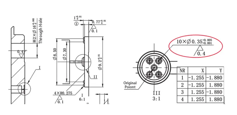
The process requirements for such holes are generally a tolerance of +0.005 mm, a surface finish of 0.4 inside the hole, a depth close to 7 times the diameter, and the workpiece material is tool steel.
The hardness is HRC48-53. All dimensions of the small holes are critical dimensions, and deviations are not permitted. Ensuring the hole diameter and surface roughness is extremely challenging.
· Processing Challenges of the Part
Previously, the company primarily used three methods to process such products: machining center cutting, EDM erosion processing, and drilling machines for pilot holes followed by slow-wire cutting.
Figure 1 Mold high-precision small hole structure diagram
The processing ranges of the three methods were as follows:
Direct drilling could process holes as small as φ0.25 (PTFE, brass), with a processing depth of 2–3 mm. Further experiments are needed for processing mold steel.
EDM could process holes as small as φ0.5, with a processing depth of 1.5 mm.
Hole punching machine: φ0.5–0.9 small holes are processed using a 0.3 electrode tube, with a depth generally less than 20 mm. This method is less affected by various conditions and has relatively stable processing performance.
φ0.4–0.5 small holes are processed using a 0.2 electrode tube, with a depth generally less than 10 mm. This method is easily influenced by factors such as processing material, water quality, electrode tube, and clamping.
As hole processing depth increases, the likelihood of deviation increases, which can cause short-circuit issues during slow-wire processing. Therefore, as processing thickness increases, the maximum processable hole diameter decreases.
Conventional slow-wire processing typically uses a 0.2 mm electrode wire. Due to the quality of the threading hole, processing holes of 0.5 mm or larger generally poses no issues.
In summary, all three methods face challenges when processing holes with diameters of 0.4 mm or smaller.
To achieve high-precision core hole processing of 0.4 mm or smaller in molds, we conducted in-depth verification of the aforementioned three methods, optimizing and improving each process.
Taking the commonly used 0.35 mm hole as an example, we verified which method can achieve qualified high-precision small hole processing with a diameter of 0.35 mm or larger.
Processing Verification
· Direct Drilling Verification on a Vertical Machining Center
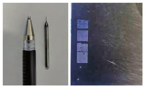
A φ0.35 drill bit has poor rigidity, low strength, difficulty in chip removal, and poor stability, making it prone to breakage.
Although some experience has been accumulated, the cutting parameters vary significantly due to differences in the materials being processed.
Only the use of a thick-shank drill and a high-dynamic-balance tool holder can be fully inherited from previous experience.
》 Principles for Adjusting Cutting Parameters
The principles for adjusting cutting parameters are generally consistent. Typically, cutting torque is reduced by appropriately increasing cutting speed and decreasing feed rate, while improving drilling stability and reducing the risk of drill bit breakage. Through actual verification, the theoretical basis is as follows:
Within the low-speed cutting range, as the cutting speed (i.e., spindle speed) increases, the drilling force decreases.
Approximately doubling the cutting speed reduces the drilling force by about 50%, while the drilling temperature increases by approximately 20% to 33%, with little effect on the drilling torque;
When the feed rate is doubled, the drilling force increases by approximately 68%, and the torque increases by approximately 85%. and the drilling temperature increases by about 10%.
Therefore, when adjusting machining parameters, it is recommended to prioritize increasing the spindle speed within an appropriate range and reducing the feed rate per revolution.
》Effects on Accuracy and Entry Positioning
This is because increasing the cutting speed and reducing the feed rate per revolution can effectively reduce drilling force and torque, although the drilling temperature may increase, it can be effectively controlled using coolant. Additionally, the smaller the feed rate, the smaller the drilling position error.
This is because a smaller feed rate results in more rotational drilling cycles during entry, thereby increasing the number of corrections for entry position errors.
Additionally, to reduce drill bit runout, we repeatedly adjusted the clamping to ensure that the diameter of the drill bit after rotation is as close as possible to its diameter when stationary.
》Verification Results and Limitations
Through the above improvements and by solidifying the processing parameters via a program template, several batches of verification parts were processed on tool steel material.
Although hole processing was successfully achieved, measurements showed that the diameter tolerance of holes directly processed by the drill bit was within the range of 0 to 0.01 mm, failing to meet the workpiece’s 0.004 mm tolerance requirement.
Additionally, the hole diameter could not be guaranteed to be consistently produced, The surface finish inside the hole also failed to meet the 0.4 requirement.
Furthermore, as the drill bit diameter decreases, the machining difficulty increases, and the drill bit is prone to breakage during machining, introducing significant uncertainty. Therefore, this approach is not feasible.
· EDM Verification
》 Electrode Machining
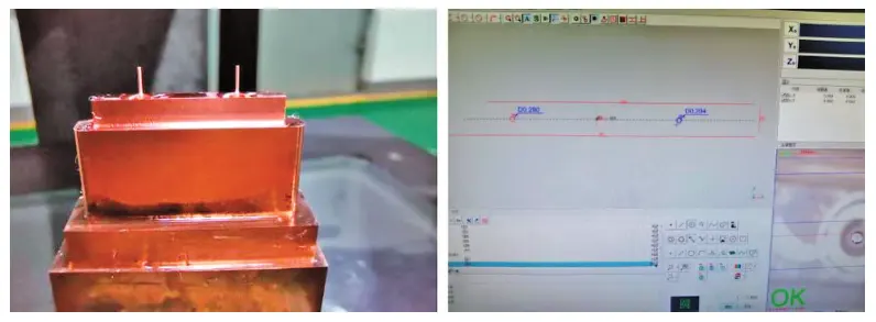
If an electrode is used to machine a φ0.35 hole, the maximum diameter of the electrode must not exceed φ0.3 mm, and the length must not be less than 3.5 mm. For copper electrode machining, a length-to-diameter ratio greater than 1:10 and a machining position accuracy of 0.005 mm present a new challenge.
First, the machining accuracy of the electrode’s cylindrical diameter must be within a tolerance of 0.01 mm (including bending deformation), and dimensional consistency must be within 0.005 mm. This ensures that the discharge current can be adjusted during EDM, thereby guaranteeing the machining accuracy of the hole diameter;
Second, the cylindrical positional accuracy must be within 0.005 mm (including bending deformation), laying the foundation for ensuring the positional accuracy of the hole during EDM.
To ensure the above processing accuracy, improvements were made from the following aspects to ensure electrode quality.
First, a layered cutting strategy was adopted, gradually adjusting the side cutting allowance and layered cutting depth to find a balance between quality and efficiency, meeting requirements without overly pursuing precision;
Second, high dynamic balance tools were selected, and a dial indicator was used to measure tool runout. The tool diameter was measured under actual machining speed conditions to control the impact of tool and tool holder precision on runout.
After multiple experiments, the cylindrical diameter consistency of the electrodes was controlled within 0.004 mm, the tolerance within 0.01 mm, the positional deviation within 0.002 mm, and the bending deformation within 0.001 mm.
》 Electrical Discharge Machining
After machining the electrode, the next step is electrical discharge drilling. Due to the electrode’s slender rod shape and poor rigidity, accurate alignment is difficult. Therefore, an alignment reference platform was added to the electrode, ensuring that the positional accuracy of the reference platform relative to the cylindrical surface is within 0.002 mm.
Through multiple processing verifications, it was found that if only one hole is processed, the precision can meet the requirements. However, when processing multiple holes, there is an issue of inconsistent hole sizes, rapid electrode wear, and difficulty in controlling the processing precision within the required range.
After verification, it was found that using EDM for hole processing results in rapid electrode wear (the thinner and longer the electrode, the faster the wear), difficulty in controlling the hole diameter, and other issues. It is also unsuitable for batch processing, making this processing method unfeasible.
· Verification of Pre-Drilling and Slow Cutting Processing Using a Drilling Machine
Previously, a φ0.2 mm electrode tube was used to process the bottom hole, resulting in a hole diameter of φ0.30–0.35 mm after processing. Considering equipment processing errors and alignment deviations (0.03 mm), this method could only meet the processing requirements for holes with a diameter of φ0.4 mm or larger.
The smallest electrode tube currently in use is φ0.15 mm. The smaller the electrode tube, the greater the post-processing deviation, and it is highly prone to erosion.
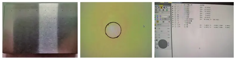
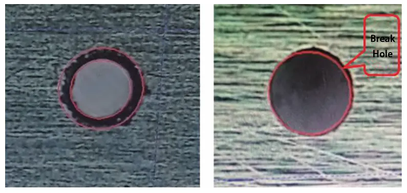
Observation revealed that upon contact with the workpiece, the electrode tube sparks, causing an explosion at the hole opening, resulting in the inability to fully cut the small hole locally, leading to an abnormally large local area of the small hole, as shown in the figure below.
》 Solutions
To reduce the occurrence of hole explosions after electrode tube processing, we conducted multiple experiments and communicated with the equipment manufacturer. By adjusting the voltage and pure water pressure, and modifying the power supply terminals, we replaced the 47 V voltage with a 33 V voltage.
We adjusted the internal circulation pressure supply water circuit, installed a pneumatic pressure-boosting water pump, increased the internal circulation pressure to enhance the water jet strength inside the hole, and improved chip removal capacity. Additionally, we adjusted the pressure gauge to 7.5 MPa.
Improving Electrode Tube Alignment and Positioning Accuracy
To reduce hole positional accuracy issues caused by alignment deviations, we observed that when the electrode tube protrudes too far, significant deflection occurs.
Therefore, we need to reduce the protrusion length of the electrode tube and establish a standard protrusion length of 1–1.1 mm.
Reduce the alignment error of the electrode tube through continuous automatic centering and alignment.
Require multiple repeated measurements in both the X and Y directions, with at least three measurements.
The error values of the last two consecutive measurements must not exceed 0.03 mm.
The measured values should closely match the actual part dimensions plus the electrode diameter.
Fine-Tuning and Stabilizing Equipment Parameters
In subsequent continuous experiments, the various electrical parameters of the equipment were continuously optimized and fine-tuned, and the appropriate parameters were finally determined and solidified.
Another φ0.15 mm electrode tube processing experiment was conducted, and when the hole diameter was processed to φ0.32 using slow wire cutting, there was no breakage at the hole opening.
In the φ0.2 mm electrode tube processing experiment, when the hole diameter was processed to φ0.33 using slow wire cutting, there was no breakage at the hole opening.
Therefore, under current conditions, φ0.15 and φ0.20 electrode tubes can be used to process holes with a diameter of φ0.35 in mold steel with a thickness of 5 mm.
Since the φ0.2 mm electrode tube has higher efficiency and a significant cost advantage, it should be prioritized for bottom hole processing.
》 Final Results
The following processing scheme was ultimately determined: For high-precision small hole processing of molds, a piercing machine is preferred, using a φ0.2 mm electrode tube for the initial hole, with slow wire cutting ensuring the final dimensional tolerance;
This scheme offers good quality, efficiency, and cost-effectiveness, and can meet actual production requirements;
Conclusion
Through repeated experimentation with various processing methods, the issue of precision small hole machining in molds was ultimately resolved using a combination of pre-drilling with a drilling machine and slow cutting for hole machining.
In this technical challenge, we built upon existing mature methods to further refine the process, achieving higher precision and quality in the product.
By redefining electrode tube parameters, we successfully machined precision micro-holes in molds, significantly expanding the company’s processing capabilities. Enhancing processing capabilities is essential to ensuring product quality and enhancing the company’s competitiveness.