


Automation technology integrates knowledge from multiple disciplines, including mechanics, electronics, and control.
It uses this integration to achieve automation and intelligence in production processes, significantly improving production efficiency and product quality.
In a fiercely competitive market environment, machinery manufacturing companies must actively adopt advanced automation technology.
By doing so, they can achieve breakthroughs in optimizing production processes, reducing costs, and enhancing product competitiveness.
This article will focus on exploring the application principles and specific practices of automation technology in the machinery manufacturing industry.
It aims to provide useful references for promoting the transformation and upgrading of China’s machinery manufacturing industry.
Overview
The principle of automation technology lies in integrating multidisciplinary knowledge, including computer technology, sensor technology, and servo drive technology.
This integration enables mechanical equipment to achieve autonomous perception, decision-making, and execution.
Specifically, an automated system typically consists of control units, drive units, execution units, and feedback units.
The control unit serves as the “brain” of the system.
It utilizes programmable logic controllers (PLCs) and industrial computers to execute predefined control algorithms and production process parameters.
This coordination ensures the real-time operation of all execution units.
Drive units employ servo motors, stepper motors, and other power devices to precisely control the position, speed, and torque output of execution units.
Take CNC machine tools as an example.
Their feed systems use high-precision ball screw pairs. When combined with linear motors, these systems can achieve nanometer-level feed resolution and positioning accuracy of ±1 μm.
They also reach speeds up to 120,000 rpm and have tool magazine capacities exceeding 240 tools.
Additionally, automated systems extensively utilize vision sensors, force/torque sensors, and other devices to real-time collect processing status information.
Through closed-loop control algorithms, they dynamically optimize processing parameters.
For instance, in precision grinding, the system measures the surface roughness Ra value of the workpiece (range 0.025–16 μm).
It then adaptively adjusts dressing parameters, significantly enhancing the flexibility and intelligence of mechanical manufacturing.
Automation technology encompasses cutting-edge fields such as CNC technology, robotics, precision transmission and drive control technology, and intelligent sensing and testing technology, representing the future direction of mechanical manufacturing in the new era.
Specific application situations
Automated production line
Automated production lines are one of the typical applications of automation technology in the machinery manufacturing industry.
The implementation process typically involves several stages, including workpiece loading, processing, assembly, inspection, and unloading.
First, workpieces are precisely fed into the processing station by feeding mechanisms such as vibrating feeders and robotic arms at a pre-set rhythm, with positioning accuracy as high as ±0.05mm;
Next, a multi-axis CNC system controls the relative motion between the cutting tools and workpieces according to the machining program, performing operations such as cutting, drilling, and milling.
The system adaptively compensates for tool wear using online measurement, ensuring that dimensional deviations during continuous machining remain within ±0.01mm.
A flexible conveyor system subsequently transports the machined workpieces to the assembly unit.
There, a six-axis industrial robot, integrated with a machine vision system, autonomously identifies the workpiece orientation (repeat positioning accuracy ±0.02mm).
It then collaborates with intelligent electric screwdrivers (torque range 0.02~5N·m) to perform precise assembly and fastening.
Finally, a coordinate measuring machine and other equipment (probe repeatability 2.0 μm) automatically inspect the assembled products for full dimensions.
The system then transmits the inspection data in real time to the MES system to optimize production scheduling.
The entire production line adopts a bus-based distributed control architecture, achieving equipment utilization rates >85% and first-pass product first-pass yield rate > 99.5%.
As such, the automated production line highly integrates mechanical, electrical, information, and intelligent algorithm technologies, achieving high-quality and efficient production through precise coordination.
CNC machine tool
CNC machine tools are also one of the most widespread and mature applications of automation technology in the mechanical manufacturing industry.
The workflow of CNC machine tools begins with importing a 3D product model into CAM software, which calculates tool paths, cutting parameters, and other data to generate NC code.
A post-processor then converts this code into G-code.
The machine tool control system parses the G-code and coordinates the movement of the feed axes and spindle.
Feed axes utilize high-precision ball screw pairs, which, when combined with AC servo motors, achieve a minimum programming increment of 1 μm and positioning accuracy of ±3 μm/300 mm.
The spindle can reach a speed of 12,000 rpm, and the system uses online vibration monitoring technology to diagnose tool wear in real time.
The tool management system automatically completes tool changes based on processing requirements and uses an in-machine probe to measure the tool tip position, achieving a repeat positioning accuracy of 1 μm.
For workpiece clamping, pneumatic chucks combined with piezoelectric sensors achieve clamping force control accuracy of ±5% FS.
During machining, the CNC system uses high-speed, high-precision servo feedback to real-time control axis movement.
For example, the linear motor’s rapid movement speed can reach 120 m/min.
Additionally, the system introduces adaptive feed rate technology based on a cutting force model, which adjusts the feed rate in real time according to machining parameters:
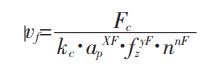
In the formula, we define Fc as the cutting force (N); ap as the cutting depth (mm); fz as the feed rate per tooth (mm/z); and xF, yF, and nF as empirical indices selected to maximize material removal rate while maintaining constant processing force.
After processing is complete, the system automatically calls upon the in-machine three-coordinate probe to inspect the workpiece, with the probe’s repeat measurement accuracy reaching 0.25 μm.
The system wirelessly transmits measurement data to the SPC system for statistical analysis.
If a deviation trend is detected, the CNC system immediately adjusts the tool compensation parameters.
The CNC machine integrates technologies from multiple fields, including CAD/CAM, servo control, and precision testing.
Through software-hardware collaboration, it achieves full-process automation, significantly enhancing processing efficiency and precision.
Robot integration
Robot integration technology, as an important branch of automation, enables flexible and intelligent production lines by closely integrating industrial robots, vision sensors, servo control, and other technologies.
The system’s operational process typically begins with the vision system precisely locating the workpiece.
The camera has a resolution of 0.05 mm/pixel, and with sub-pixel interpolation algorithms, it can achieve a repeatability accuracy of 0.01 mm.
Next, the robot controller performs coordinate transformation based on visual feedback.
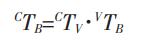
In the equation: CTB is the homogeneous transformation matrix from the robot base coordinate system to the camera coordinate system;
CTV is the homogeneous transformation matrix from the camera coordinate system to the workpiece coordinate system;
VTB is the homogeneous transformation matrix from the workpiece coordinate system to the robot base coordinate system, used for real-time planning of the motion trajectory.
The robotic arm uses harmonic reducers paired with torque motors, with a maximum load capacity of 1,300 kg and a repeatability accuracy of ±0.08 mm.
The motion control algorithm integrates variable gain PID and feedforward compensation technologies, achieving a trajectory tracking error of <0.05 mm.
Additionally, the system incorporates artificial intelligence algorithms such as virtual teaching and programming based on CAD models and dynamic obstacle avoidance, enabling autonomous planning for complex processes.
For example, in aircraft component assembly, the robot can adaptively plan the drilling sequence for rivet holes and the riveting trajectory, achieving drilling positioning accuracy of 0.02 mm and assembly
efficiency is improved by over 5 times.
Meanwhile, force/torque sensors monitor riveting force in real time, automatically adjusting parameters when deviations exceed ±10%.
The robot integrated system achieves intelligent closed-loop control through the “perception-decision-execution-feedback” process.
It breaks through the flexibility bottleneck of manufacturing equipment and provides a new engine for the transformation and upgrading of the mechanical manufacturing industry.
Application Case Analysis
Case Background Overview
At a large gear manufacturing company I am involved with, the management decided to introduce automation technology into the gear processing workshop to improve production efficiency and product quality.
The workshop primarily produces involute straight gears and helical gears with module sizes ranging from 2 to 10, using materials such as 20CrMnTi and 17CrNiMo6, with an annual production capacity of 100,000 pieces.
Currently, the company’s gear processing methods mainly involve hobbing and shaping, which suffer from frequent changeovers (average 2 hours per change), unstable processing accuracy (tooth profile error > 0.02 mm), and long production cycles (clamping time > 1 minute per piece).
Additionally, workers primarily rely on their experience for processing parameters, making it difficult to optimize cutting conditions.
As a result, tool life varies significantly (150–500 pieces per tool).
Furthermore, manual inspection primarily handles product quality checks, leading to low efficiency (<20 pieces per hour) and poor accuracy (repeatability error >0.01mm).
To address these challenges, the company urgently needs to adopt automated technologies such as CNC, robotics, and online inspection.
By doing so, it can achieve automated upgrades and renovations in gear manufacturing processes, significantly enhancing labor productivity and product competitiveness.
Analysis of Automation Technology Application Solutions
To address issues such as low efficiency, poor precision, and insufficient automation levels during production, gear manufacturing companies have designed a comprehensive automated technology application solution.
The solution deeply integrates technologies such as CNC machining, robotics, machine vision, and automatic detection, covering all stages from raw material processing to finished product inspection.
1.The DS200M CNC turning center machines gear blanks in the turning process.
A FANUC 0i-TF CNC system equips this machine, enabling it to efficiently machine blanks with high quality through graphical programming and precise tool path control.
The machine features a direct-drive spindle with a maximum speed of 6000 rpm and a rated power of 30 kW.
Paired with the Sandvik Coromant T-Max P turning tool (tool insert model CNMG120408-M3TP2501, rotational accuracy 0.003 mm), the machine can reduce the blank processing cycle time to less than 30 seconds.
2.The rough machining process uses a YK7232 CNC gear hobbing machine, equipped with a SIEMENS 828D CNC system and Liebherr hobbing cutters.
The module range is 2–10 mm, with a hobbing speed of up to 500 mm/min and gear tooth accuracy of ISO 6 grade.
The Renishaw RMP60 high-precision contact probe (repeatability 2μm) precisely measures the workpiece reference surface, enabling automated workpiece reference positioning and changeover.
3.In the finishing process, the Samputensili S800 gear grinding machine is introduced.
A SIEMENS 840D sl CNC system equips this machine tool, and it combines with a Schneider BSH1202P31A2A servo motor (rated torque 120 N·m, encoder resolution 23 bits) to achieve high-precision, constant-power cutting.
The maximum linear speed of the grinding wheel is 80 m/s, and the dressing process uses a diamond roller for online centerless dressing, achieving a dressing accuracy of ±2 μm.
During the machining process, the machine tool continuously collects data from the Kistler 9345B piezoelectric force sensor.
It also uses the Marposs P7M probe (repeatability 0.4 μm) to measure the tooth profile.
This establishes a closed-loop feedback system that achieves controllable optimization of tooth profile accuracy (error <0.5 μm).
4.In the clamping and handling process, the solution integrates the FANUC RM-710iC/50 robot (rated load 50 kg, repeatability ±0.07 mm) and the Keyence CV-X420F machine vision system.
First, the vision system captures workpiece images using a coaxial light source and a 2/3-inch CCD camera.
It employs a sub-pixel edge detection algorithm (resolution 0.02mm) to obtain workpiece pose information, guiding the robot to achieve precise gripping (positioning accuracy ±0.05mm).
In terms of end-effector design, the system uses a customized flexible pneumatic gripper and pairs it with a Tekscan pressure sensor (resolution 0.7 kPa) to monitor gripping force in real time.
Through a fuzzy PID algorithm, gripping force is precisely controlled (error < ±6% FS), ensuring a gentle handling process during clamping.
5.The inspection process utilizes the Jenoptik Hommel EtamicW5 coordinate measuring machine.
This equipment is equipped with a VAST XTR probe (measuring force <0.05N) and a Renishaw SP25M analog scanning probe (repeatability 0.25μm), enabling fully automatic dimensional inspection of gears (dimensional deviation <2μm).
The probe features a three-dimensional inverse kinematics design, ensuring that the contact force during measurement remains perpendicular to the surface being measured, thereby effectively reducing probe wear.
Additionally, the measurement process employs online probe calibration and temperature compensation technology to ensure the long-term stability of the equipment.
In terms of inspection efficiency, the system integrates a honeycomb fixture and a dual-station turntable, enabling parallel operations for clamping and measurement, with single-piece inspection time controlled within 60 seconds.
Inspection data is uniformly uploaded to the MES system, where SPC statistical algorithms are used for process capability analysis, monitoring processing quality levels, and warning of deviation trends, as shown in Table 1.

Through the systematic integration and optimization of automation technology, it builds a highly flexible and intelligent gear production line.
This line maximizes quality and efficiency while minimizing human intervention, laying the foundation for the realization of intelligent manufacturing.
Conclusion
This paper systematically explores the application of automation technology in the machinery manufacturing industry.
It demonstrates the technology’s advantages in enhancing production efficiency, improving product quality, and reducing costs through specific case analyses.
By introducing technologies such as CNC machining, robot integration, and automatic detection, the company has fully automated the entire process from raw material processing to finished product inspection.
This automation significantly enhances the flexibility and intelligence of production lines.
Future work can continue to optimize the intelligent algorithms of automated systems and enhance their adaptability and stability.
This will help address more complex and diverse production requirements and drive the mechanical manufacturing industry toward more efficient and intelligent development.