


In the field of mechanical engineering, flange is a common connecting part, which is widely used in various mechanical equipment. The main function of flange is to connect two pipes, equipments or components so that they can move with each other and transfer the force.
Some complex flanges need to have a certain bearing capacity, sealing performance, flexibility of movement, and even work under high pressure and high temperature. Therefore, its mechanical manufacturing process is a very complex process, need to think carefully about each step to ensure the overall quality of the product.
In this paper, the design of the flange machining process procedures and a process in a special milling fixture, under the premise of ensuring the accuracy of the parts processing, improve the processing efficiency, reduce labor intensity, for the processing of similar parts to provide a reference.
Parts structure and process
Flange is used to connect the parts, strengthen the fixity between the parts, with the role of support guidance, wear resistance, stability and strength requirements are high.
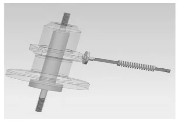
In this paper, the flange is used to connect the spindle and chuck, the structure of the part is centered on Φ20mm (+0.045/0) holes, consisting of 4 rotary surfaces and 2 planes, and the inside of the part consists of 1 stepped hole and 4 Φ9mm through holes.
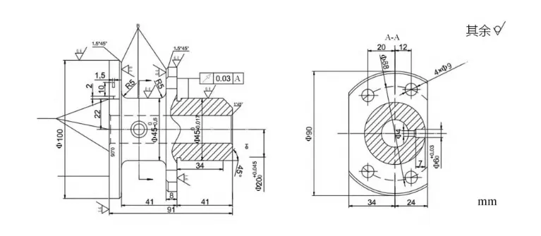
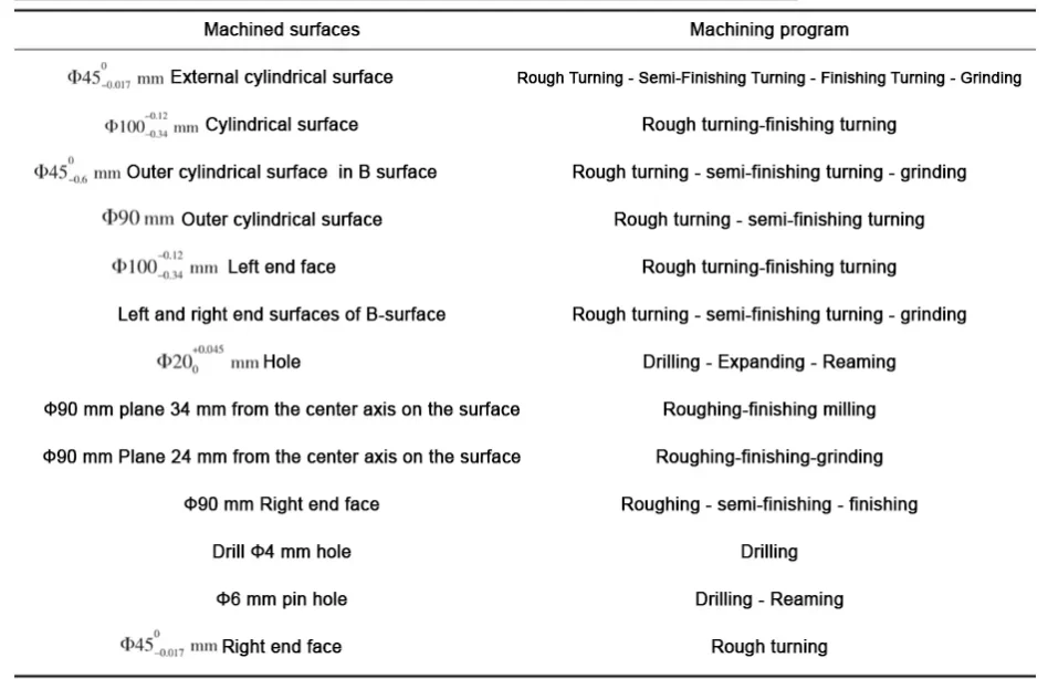
Machining surface to Φ20 (+0.045/0) mm hole as the center, tolerance level IT8IT9, machining part of Φ100 (-0.12/-03.4) mml cylindrical surface, roughness 0.8mm, tolerance level -0.12 for IT11;.
Ф100 (-0.12/-0.34) left end face, roughness R is 1.6;
Φ45(0/-0.6)mm cylindrical surface on B surface, roughness R is 0.4mm, tolerance class IT14;
The left and right end surfaces on the B surface have a roughness Ra of 0.4mm; the Φ90mm cylindrical surface has a roughness Ra of 6.4mm;
Roughness Ra is 3.2mm for the Φ90mm surface 34mm from the axis;
Roughness Ra of the Φ90mm surface 24mm from the axis is 0.4mm;
The surface of Φ90mm has four Φ9mm 0 holes;
Φ45 (0/-0.017) mm cylindrical surface, roughness Ra is 0.8 mm, tolerance class IT6.
Process design
Selection and determination of blank
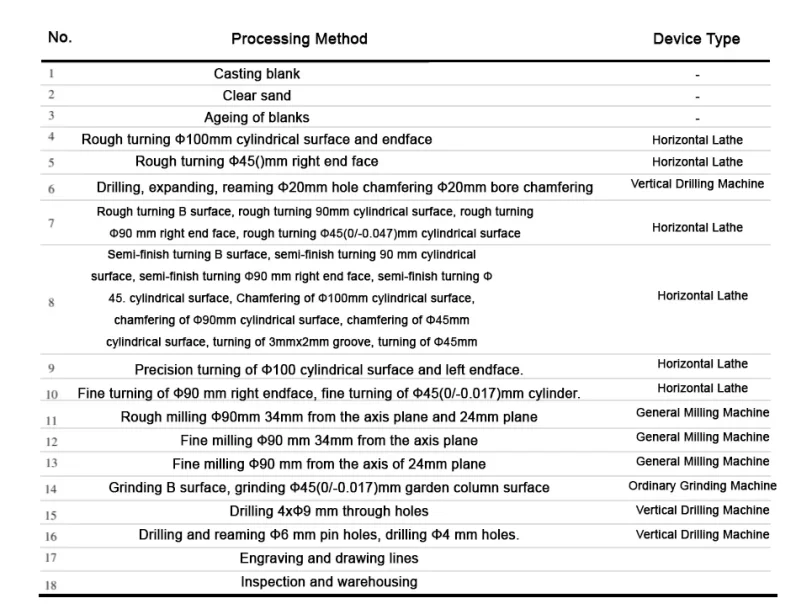
Flange material for HT200, simple structure, parts production batch for the medium batch production, parts contour size is not large, so the blank is produced by casting, which helps to improve the production and processing efficiency and ensure the processing quality.
Development of machining process route
According to the principle of processing surface dimensional accuracy and surface roughness to meet the requirements of the principle of selected processing methods and processing stages, to get the flange parts surface machining program, as shown in Table 1.
On the basis of determining the surface machining program, follow the first rough and then fine, the first face after the hole, the benchmark first, the first main after the second principle, the development of the flange machining process route, as shown in Table 2.
Milling plane fixture design
The designed fixture should not only meet the requirements of the limitations of the degree of freedom, but also consider the rapid disassembly of the workpiece, but also to achieve more standardized parts and simple structure to ensure the quality of machining, reduce the cost of manufacturing fixtures, save workpiece clamping time, improve production efficiency.
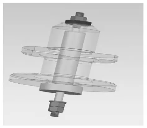
Positioning program
The special fixture is used for finish milling the plane 24mm from the axis on the Φ90mm face in process 13, the roughness of the plane is 0.4mm, and there is a requirement of shape and position with the centerline of the center hole Φ20mm.
Therefore, the hole of Φ20mm and the bottom face of Φ100mm are used as the main positioning to limit 5 degrees of freedom, and then the plane on the side of Φ90mm which is 34mm away from the axis is used as the auxiliary positioning to limit 1 rotation, i.e., the positioning of one hole and two faces is used to realize the complete positioning.
The positioning scheme is shown in Figure 2.
Clamping program
The fixture is mainly positioned with Φ20mm hole and Φ100mm bottom face, in order to ensure that the positioning is not destroyed, so the spiral clamping is selected to provide a large mechanism expansion force ratio, high clamping efficiency, good self-locking.
The spiral clamping mechanism selects the combination of cotter washer material and hexagonal nut, rotate to loosen the M8 nut, draw out the cotter washer, and withdraw the workpiece from the positioning pin to realize the quick dismantling of the workpiece;
When loading the workpiece, first install the workpiece into the positioning pin, then insert the cotter washer and tighten the nut, the disassembly process does not need to remove the nut, which shortens the auxiliary working hours and ensures the production rhythm. The clamping scheme is shown in Figure 3.
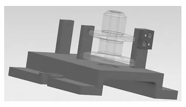
Guiding element
This process is a side plane machining, only to ensure that the tool and the machining surface of the left and right distance, the height of the distance does not need to ensure that the choice of square to the tool block and side. The installation of the counterblock is shown in Figure 4.
Clamp specific
Clamp is the base and skeleton of the fixture, mainly used for installing and fixing the positioning element, clamping element and tool setting block.
According to the size and shape of the entire mechanism to adjust the structure of the specific size of the clamp, can ensure the stability of the mechanism. In this paper, the design of the fixture is shown in Figure 5.
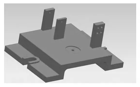
The clamp is used for the positioning of the workpiece and the fixing of the tool setting block. The surface consists of Φ42mm holes and Φ8mm holes to fix the pin of the positioning element;
The surface consists of 2 plates and 4.2mm x 4.2mm square holes for fixing the positioning element, and 1 set of spring mechanism consisting of a spring-loaded square rod and a split plate, and 1 plate for fixing the square tool setting block.
This plate consists of two Φ5mm holes and two Φ6mm holes, which can be assembled with hexagonal screws and cylindrical pins to ensure the stability of the fixture structure.
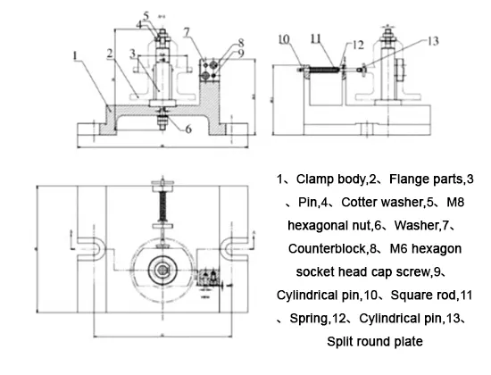
Fixture Assembly Diagram
Figure 6 shows the general assembly diagram of the fixture. The fixture has a clamp body as the base, a positioning pin and a spring mechanism consisting of a square rod, a spring and a split plate on the side, which is used to locate the workpiece;
The fixture is fitted with a square tool setting block for tool setting;
The workpiece is mounted on the fixture by means of a positioning element and clamped by means of a screw clamping mechanism (consisting of a nut and an open washer).
Conclusion
By analyzing the structural characteristics and processing requirements of the flange, this paper formulates a reasonable machining process, and designs a special fixture for one of the processes.
Process regulations are mainly designed to design the manufacturing method of blanks and analyze the machining process of the workpiece, the special fixture is the design of positioning elements, clamping elements, tooling blocks and clamping specific.
Through the research and design of flange parts machining process, can ensure the machining size and accuracy of the workpiece, but also can provide a new method for the processing of similar parts.
The application of this process in parts machining can significantly improve productivity, reduce product loss, and obtain higher economic returns.