


In recent years, due to the increasing awareness of environmental protection, electric vehicles have become more and more popular among consumers.
To produce high-quality electric vehicles, manufacturers must use high-quality injection molded parts for the heat exchangers.
As an important part of the heat exchanger, injection molded parts must be extremely stable to ensure the safe and efficient operation of electric vehicles.
Fusion lines commonly form in injection molded parts and reduce the product’s appearance quality and mechanical properties.
At present, the main way of determining whether or not a defective wire is present in an injection-molded part is to use the naked eye. This method relies on subjective judgment and is less accurate.
At the same time, working for a long time in an environment full of pungent chemical and plastic odors has a certain impact on the health of workers.
Application of Machine Vision in Defect Detection
Adopting machine vision can effectively solve the above problems.
As artificial intelligence rapidly develops, researchers and engineers widely use machine learning in defect detection.
Some experts et al. designed a defect detection system based on machine vision for nickel-based high-temperature alloy bar surface defects.
First, researchers pre-process the images using Gaussian filtering, adaptive binarization, and morphological methods.
Then, they apply Canny edge detection and contour finding to locate the defects’ contours.
Finally, they integrate the relative coordinates of the defects, the camera position, and the angle of the bar to achieve the defect detection goal.
Finally, the system integrates the relative coordinates of defects, the camera position, and the bar angle to achieve the goal of defect detection.
Advances in Machine Learning-Based Inspection Systems
Another experts et al. proposed a machine vision-based surface defect detection method for small-sample automotive parts, using a guide frame region candidate network to improve the region candidate network of the Faster RCNN detection network, and utilizing a focused loss function to improve the positive and negative sample imbalance to achieve the detection of surface defects on small-sample parts.
Some engineering proposed a lightweight mango surface defect detection algorithm based on YOLOv5, which can effectively reduce the performance requirements of the deployed equipment and lower the cost of the inspection equipment.
Another engineering proposed a detection algorithm with low computational effort and high stability, which first decomposes the image using the non-down sampled shear wave transform, then filters the decomposed high-frequency components and performs image enhancement, and finally reconstructs the original image using the non-down sampled shear wave transform, combining morphological operations and the Sobel algorithm to realize defect detection.
Someone proposed an improved EfficientNetV2 network for the recognition of defects on wire mesh surfaces.
Firstly, researchers add channel splitting and channel conversion before and after feature extraction.
Then, they gradually compress the extracted high-level semantics.
Finally, they build the image acquisition system to construct a dataset, which supports the detection of defects on wire mesh.
Experts designed a packaging quality inspection system, firstly, using median filter to eliminate image noise, then using Canny algorithm to achieve edge sharpening, and finally, realizing defect detection through image alignment.
Another engineering designed a thread defect detection method based on machine vision, proposed an efficient thread feature extraction method, and established a thread defect dataset to effectively improve the efficiency of thread detection.
The article combines the existing machine vision technology to carry out online inspection of the beam of the injection molded part to determine whether the beam of the injection molded part meets the production standards, so as to make the overall production of injection molded parts safer and more reliable.
Defect type
The defect studied in this article is a weld line, as shown in Figure 1.
During the injection molding process, high injection speed causes weld lines to form at the intersection of the material streams.
Defects mainly occur in the beam areas of the molded part, especially in the middle section of the beams.
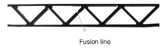
Fig. 1 Schematic diagram of fusion line defects
Its length of the injection molded part is 870 mm and the width is 510 mm, as shown in Figure 2a.
Inspectors examine both the front and back sides of the part.
Easily inspected areas, such as shrapnel, clips, and through holes, are concentrated at the left and right ends, while the beams lie in the middle.
During the production of injection molded parts, the machine injects material from two points, A and B.
Fusion lines mainly form at the intersection of the material flow, so the two vertical beams in the middle do not generate fusion lines and do not require inspection.
The length of the beams varies from one area to another, but the width of the beams is the same, with a value of 3 mm.
To capture a clear and complete image of the entire beam area, the team used an FA lens with a focal length of 8 mm, positioned 260 mm from the beams, based on the length of the beams (210 mm on the long side), as shown in Fig. 2b.
The captured image has a resolution of 2,448 × 2,048, a field of view of 260 mm × 170 mm, and the visual analysis formula appears in Equation (1).
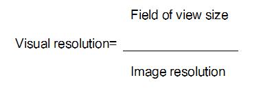
The system obtains a visual resolution of 0.0088 mm per pixel.
Inspecting the beam area in a straight line helps detect complete breaks more effectively, but makes it difficult to detect fused wires.
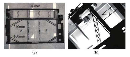
Fig. 2 Schematic structure of injection molded part
(a)Injection molded part (b) Beam
Fusion Wire Inspection Methods
The article proposes a fusion line detection method using skeleton extraction and slope judgment.
It is mainly divided into 3 steps:
1. Image pre-processing
Morphological operations and Gaussian filtering eliminate reflective interference in the acquired original image, while binarization highlights the beam edge information.
2. Extraction and cutting of defective regions
Combine the processed images and first apply template matching to extract the beam region.
Then, extract its skeleton and use polygonal approximation on the skeleton to find a line that meets the threshold.
Finally, apply affine transformation based on the found line to cut the region to be detected.
3. Defect identification
Finally, use the found line to apply an affine transformation and cut the region to be detected.
On the extracted edges, take points at fixed intervals and connect them to form a straight line.
Then, calculate the slope of each straight line, and when the slope exceeds the set threshold, the system flags it as defective.
When the slope exceeds the set threshold, the system recognizes it as defective.
The flowchart of weld line detection is shown in Fig. 3.

Fig. 3 Flow chart for fusion line inspection
-
- Image Preprocessing
During image acquisition, background light interferes with the image, making it difficult to extract the complete beam region.
Based on the characteristics of the disturbed area, apply a Gaussian filter to smooth the edges of the image.
Then, use morphological operations to eliminate background light interference.
Finally, apply the Otsu method to binarize and highlight the edge information of the beams.
The pre-processed image is shown in Fig. 4.
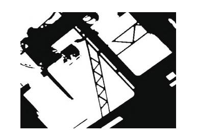
Fig. 4 Pre processed image
-
- Cutting method based on skeleton extraction
1. Template Matching
Template matching is the most commonly used method in image processing because it allows users to find the part of the large image that most closely matches the template image.
To facilitate subsequent image processing, the system intercepts the matched image, and it shows the result in Fig. 5.
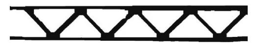
Figure 5 Template Matching Intercept Result
2. Skeleton Extraction
To cut the image more effectively, the system first extracts the skeleton of the beam.
The system can achieve better results with the skeleton extraction method.
Common skeleton extraction methods include refinement algorithm, skeleton extraction algorithm based on axis of symmetry analysis and shape decomposition method.
In this article, we use the refinement algorithm to process the image data.
Zhang⁃Suen algorithm is a common refinement algorithm.
Compared to other skeleton extraction algorithms, this algorithm offers high execution efficiency, so we choose it.
The image after skeleton extraction is shown in Fig. 6a.
From the figure, we can see issues such a noise interference and discontinuity of the skeleton.
Therefore, apply Gaussian filtering to eliminate noise in the image.
Then, use the Otsu method to clarify the image edges.
Finally, connect the skeleton using a one-time corrosion and expansion method, as shown in Fig. 6b.
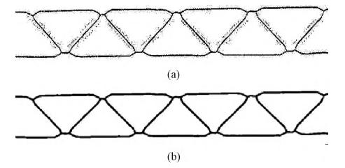
Fig. 6 Skeleton extraction diagram
(a)Skeleton extraction (b) Skeleton optimization
3. Image Cutting
Image cutting is the technique and process of dividing an image into several regions with unique properties and presenting a target of interest.
Based on the characteristics of the image, we use an edge-based cutting method.
The image cutting algorithm based on polygon approximation belongs to the edge-based cutting method, which cuts the image according to the edge features in the image.
The specific steps are:
(1) The classical Canny algorithm performs edge detection to find the beam edge in the image and records the edge information.
(2) The Douglas-Peucker algorithm approximates multiple edges on the found beam edge, and the approximated image appears in Figure 7.
Douglas-Peucker algorithm is a recursive-based algorithm for polygonal approximation of folded lines.
The Douglas-Peucker algorithm approximates multiple edges of the found beam edge, and the resulting image is shown in Figure 7.
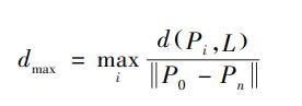
Where: P0 and Pn are the starting point and the end point of the folding line; L is the straight line composed of P0 and Pn; d (Pi, L) represents the distance from Pi to the straight line L.
The algorithm is easy to implement because it adopts a recursive approach. Since the algorithm adopts a recursive approach, it is easier to realize.
(3) Based on the found polygon vertices, calculate each edge of the polygon.
The results are shown in Table 1, and the polygon image is shown in Fig. 8.
The extracted image of the skeleton has a horizontal pixel count of 414 pixels.
The system calculates the pixel scale as 2.5 pixels/mm, based on the actual length of the beam in the field of view, which is 160 mm.
Since the system divides the actual length of the beam into 30 and 40 mm sections, it sets the threshold value for a section of the beam at [60, 130].

(4)set the ROI area based on the retained straight line information, and Fig. 9a shows the ROI area.
Based on the ROI area, apply affine transformation to obtain the image of each beam section. The affine-transformed image appears in Fig. 9b.
Use matrix operations to achieve the specific transformation effect.
The affine transformation formula is shown in Equation (3).
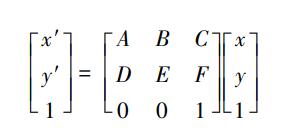
Where: (x, y) are the chi-square coordinates of a point in the original image;
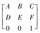
is the affine transformation matrix; It is the affine transformation matrix; The system obtains the chi-square coordinates (x′, y′)(x′, y′) of the corresponding points in the transformed image by performing the matrix multiplication operation.
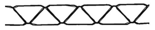
Figure 7 Polygon Approximation
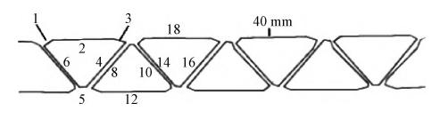
Figure 8 Polygon diagram
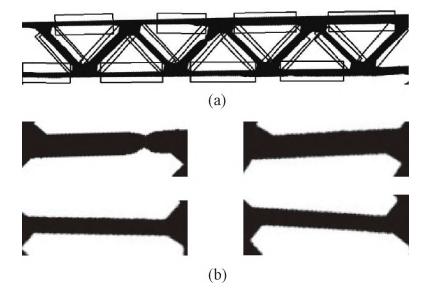
Fig. 9 Image cut map
(a)ROI region (b) Result after affine transformation
-
- Slope Judgment Method
-
- 1. Apply the Canny edge detection operator to extract edges from the segmented beam region and obtain the edge point set.
-
- 2. Select points from the edge point set at fixed intervals to form the interval point set.
The results are shown in Table 2, and the image of the interval points is shown in Fig. 10.
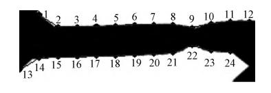
Figure 10 Interval point images
-
- 3.Connect two points on the same edge and calculate the slope k of each line from the slope formula.
The slope formula is shown in equation (4).
Where (x1, y1) and (x2, y2) represent the coordinates of two known points in the original image.
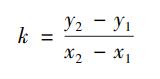
Table 3 shows the results, listing the slopes of the upper edge in rows 1 to 4 and the slopes of the lower edge in rows 5 to 6.
For straight lines on the same edge, set the slopes of the first and last lines to zero to avoid influencing the slope.
The fusion line forms at the intersection of the material streams, which does not occur at the ends of the beams and, therefore, prevents missed inspection.
Fig. 11 shows a line graph of the slope of the straight lines.
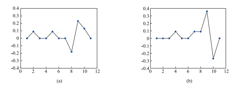
Figure 11 Linear slope line graph (to avoid interference, the slopes of the first and last line segments are set to 0)
(a)Linear slope line graph of the upper edge (b) Linear slope line graph of the lower edge
-
- 4. Set a threshold (after many experiments, the empirical value of [0. 15, – 0. 15] is finally chosen as the judgment threshold, which corresponds to the actual tilt angle of about 8. 53°), and when the slope k of a line segment exceeds this threshold, it is judged that there is a defect in the region, otherwise the region is normal.


In specific experiments, other types of defects, such as flying edges, may exist at the edge of the beam and affect the slope, resulting in misjudgment.
To eliminate misjudgment, the system sets a rule based on the characteristic that defects distribute at the two ends of the beam: when 2–4 line segments have abnormal k values in the region and these segments distribute symmetrically, the system judges the presence of defects in this region and marks them accordingly.
This approach helps avoid misjudgment, and it shows the defect detection results in Fig. 12.
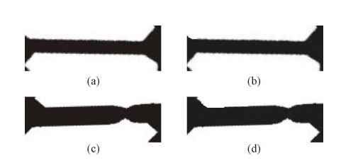
Fig. 12 Defect detection results
(a)True Normal (b) Predicted Normal (c) True Defect (d) Predicted Defect
Results and discussion
The team developed the experimental code using the PyCharm 2023 integrated development environment, the Python 3.9 programming language, and the OpenCV-Python 4.7.0.72 machine vision library.
The hardware system mainly consists of Hikvision industrial camera MV-CS050-10GM, Hikvision FA lens with a focal length of 8mm, Hikvision LED ring white light source, and Fanuc LR MATE 200iD/4S robot.
The experiment simulates the actual factory production, and adopts the slope judgment method and the straight line inspection method to inspect 100 injection molded parts respectively.
First, the robot grips the injection molded parts placed in the equipment’s loading area and places them onto the conveyor belt.
Then, the conveyor belt transfers the parts to the visual inspection area for photographing and inspection. Finally, the system outputs the inspection results in real time.
The experiment collects a total of 400 images of the beam area, including 354 normal samples and 46 fusion line samples.
Comparing the two methods, Table 4 shows the results of the slope judgment method, and Table 5 presents the results of the straight line detection method.
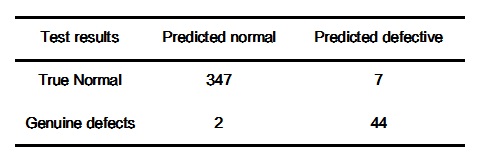
Table 4 Detection results of slope judgment method
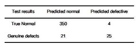
Table 5 Results of straight line testing methods
Analyzing the test data in Table 45, we find that the slope judgment method has a 2% misdetection rate, a 4.3% leakage rate, and 97.8% accuracy; while the straight line detection method has a 1% misdetection rate, a 45.6% leakage rate, and 92.7% accuracy.
Analysis of the test data in Table 45 shows that the slope judgment method has a 2% misdetection rate, 4.3% leakage rate, and 97.8% accuracy, while the straight line detection method has a 1% misdetection rate, 45.6% leakage rate, and 92.7% accuracy.
Conclusion
-
- The skeleton extraction method has reference value for the fusion line generated on the beam, which provides a better basis for the subsequent segmentation of the defects.
-
- The slope judgment method can meet the requirements of detecting defects with a length of 2mm and a depression angle of more than 8.53°, but it is difficult to detect defects with a depression angle of less than 8.53°.
-
- Compared with the linear detection method, the slope judgment method increases the false detection rate by 1%, improves the accuracy rate by 5%, and significantly reduces the leakage rate.