


Today, CNC Technology is Widely Adopted by the Global Manufacturing Industry. In order to improve manufacturing capabilities and standards, as well as enhance adaptability and competitiveness in dynamic markets, CNC (Computer Numerical Control) technology is widely adopted worldwide. Currently, high-end CNC equipment exhibits the following development trends:
- Improved geometric accuracy of machine tools and higher control precision of motion trajectories, with significantly enhanced processing speed and efficiency.
- Constant improvement in machining precision, repeatability, and reliability, enabling stable performance over the long term and allowing multiple processing tasks under varying operational conditions.
- Emergence of many high-performance and highly reliable functional components, such as high-frequency electric spindles, linear motors, torque motors, and electric ball screws.
- Increasing intelligence of machine tools, along with the rapid development of advanced CNC systems, leading to more intelligent, open, and networked CNC equipment with features like self-optimization, self-monitoring, self-diagnosis, and predictive maintenance.
High Speed, High Precision, and High Efficiency Are Mainstream Trends
High-speed cutting refers to cutting at speeds 5 to 10 times faster than conventional methods.
High-speed machining—especially high-speed milling—is closely related to the development and application of a new generation of high-speed CNC machine tools, particularly high-speed machining centers.
In the past decade, continuous advancements in tooling, servo drives, digital control, and machine tool technology have enabled high-speed and high-precision machining. High-speed cutting (HSM) is now widely used and promoted in aviation, aerospace, and mold manufacturing industries.
In many cases, traditional electrical discharge machining (EDM) has been replaced by high-speed cutting.
By using high-speed milling to perform integrated processing on mold blanks in a single clamping, not only is the machining accuracy and surface quality significantly improved and processing time greatly reduced, but production processes are also simplified—shortening manufacturing cycles and lowering production costs.
- In the automobile industry, for instance, a production rate of 300,000 vehicles per year means a cycle time of 40 seconds per vehicle, and multi-variety processing is a key challenge that automotive equipment must address.
- In the aerospace industry, components often involve thin walls and ribs, with poor stiffness, made of aluminum or aluminum alloys. These can only be machined under high cutting speeds and low cutting forces. In recent years, large monolithic aluminum blanks are “hollowed out” to form wing and fuselage structures, replacing multiple parts joined by rivets, screws, or other connectors. This approach enhances the strength, stiffness, and reliability of structural components.
All of this raises requirements for high-speed, high-precision, and high-flexibility machining equipment. To meet these demands, supporting components such as electric spindles and linear motors have rapidly developed and found broader application.
High-frequency electric spindles, linear motors, electric ball screws, torque motors, and high-speed cutting tools are increasingly used in high-end CNC equipment.
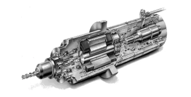
(1) High-Frequency Electric Spindles (Figure 1)
A high-frequency electric spindle directly integrates the motor into the spindle unit, eliminating the need for transmission components. It is a combination of a high-frequency motor and spindle assembly, featuring compact size, high speed, and stepless speed regulation.
Its compact structure includes inner and outer bearing rings made from high-nitrogen alloy steel, ceramic rolling elements, and advanced sealing and cooling technologies to support high-speed operation.
This technology represents an integration of precision manufacturing, bearing technology, motor speed regulation, and motor technology. International high-speed, high-precision CNC machines widely adopt electric spindle units.
In multi-tasking machining centers, multi-axis multi-face machining machines, parallel kinematic machines, and flexible machining units, electric spindles offer advantages that mechanical spindles cannot match.
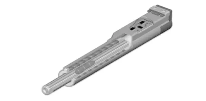
(2) Linear Motors (Figure 2)
Linear motors are specifically designed for machine tools requiring high dynamic performance and motion accuracy. Although more expensive than traditional servo systems, they greatly simplify mechanical transmission structures and significantly improve dynamic performance.
- In terms of feed speed and acceleration, linear motors can reach up to 30 g. Currently, machining centers can achieve feed accelerations of 3.24 g, and laser processing machines up to 5 g.
- Machines driven by linear motors with feed speeds of 100 m/min and accelerations of 1 g to 2 g are now common.
- Siemens’ 1FN1 series of three-phase AC permanent magnet synchronous linear motors can achieve speeds of 120 m/min and acceleration of 2 g.
- Germany’s TRUMPF and France’s Renault Automation offer linear motors with speeds of 150–200 m/min and accelerations up to 5 g.
In terms of positioning accuracy, linear motors combined with optical grating closed-loop control can achieve positioning accuracy of 0.01–0.1 μm.
Using feedforward control, linear motor drive systems can reduce tracking errors by more than 200 times.
Thanks to excellent dynamic characteristics of moving parts, sensitive response, and refined interpolation control, nanometer-level control can be achieved.
As for travel length, traditional ball screw transmission is limited by manufacturing techniques, typically allowing 4–6 meters. Longer travel requires screw extensions, which are less ideal in both manufacturing and performance.
In contrast, linear motors allow indefinitely long stators, with simplified manufacturing processes. Large machining centers now achieve X-axis travel exceeding 40 meters.
Linear motor-driven platforms offer high speed, high acceleration, high precision, and unlimited travel, making them an ideal match for the demands of modern CNC feed servo motors.
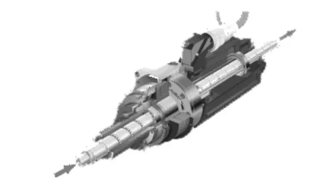
(3) Electric Ball Screw (Figure 3)
The electric ball screw integrates a servo motor with a ball screw, offering several advantages such as fewer transmission components and a compact structure.
By using electric ball screws, the structure of CNC machine tools can be greatly simplified.
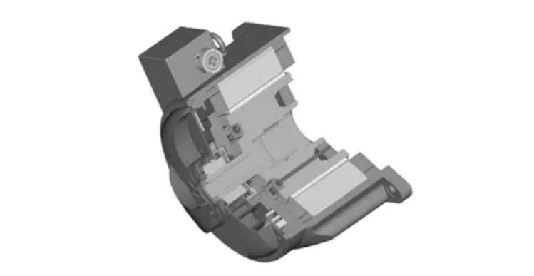
(4) Torque Motor (Figure 4)
In high-speed machining centers, motions such as swiveling rotary tables and swinging or rotating fork-type spindle heads are now widely driven by torque motors.
A torque motor is a synchronous motor whose rotor is directly mounted on the component to be driven, meaning no mechanical transmission parts are needed—just like a linear motor, it is a direct-drive device.
Torque motors can achieve angular acceleration that is six times higher than that of traditional worm-gear drives. When applied to swinging fork-type spindle heads, acceleration can reach 3g.
Because torque motors achieve very high static and dynamic load rigidity, they improve positioning accuracy and repeatability of rotary and swing axes.
(5) High-Speed Cutting Tools
Tool material advancements are one of the decisive factors in the progress of cutting technology. Tool materials play a critical role in high-speed cutting.
In the past 30 to 40 years, breakthroughs in tool materials have solved many challenges in high-speed cutting.
- New tool materials such as ceramics made of oxides, carbides, and nitrides, as well as cubic boron nitride (CBN) tools, have excellent heat resistance.
- Whisker-reinforced ceramic tools and coating technologies have significantly improved tool hardness, enabling tools to have hard cutting edges and tough substrates.
- Polycrystalline cubic boron nitride (PCBN) inserts, produced via polycrystalline methods, have a hardness of HV 3500–4500 and have become the preferred tool for high-speed cutting of hardened steel.
- Similarly, polycrystalline diamond (PCD) inserts, also made by polycrystalline methods, can reach hardness values of HV 6000–10000. Tools made from PCD materials (such as turning tools, milling cutters, and drills) can be used for high-speed cutting of non-ferrous metals, and sometimes even for cutting ferrous metals.
It is worth noting that the combination of direct-drive linear axes and direct-drive rotary axes enables all motion axes of the machine tool to achieve high dynamic performance and excellent regulation characteristics, creating ideal conditions for high-speed, high-precision, and high surface-quality free-form surface machining.
The emergence of these high-performance and highly reliable new functional components has shortened the development and prototyping cycles of CNC machine tools and greatly improved their performance and reliability.
In addition…
As the performance of functional components improves significantly, there are new requirements for the control accuracy of high-end CNC equipment. Large international CNC manufacturers have proposed the concept of nano-interpolation.
In China, Tianjin Tianda Jingyi CNC Technology Co., Ltd. has adopted nano-level interpolation technology in its latest embedded CNC system, TDNC-SX.
Reliability of High-End CNC Equipment
The reliability of CNC machine tools is a key quality indicator for CNC products.
Whether a CNC machine tool can fully utilize its high performance, high precision, and high efficiency, and deliver good economic results, depends critically on its reliability.
A key quantitative measure of reliability is the Mean Time Between Failures (MTBF).
- For CNC systems—the “brain” of CNC machine tools—MTBF has increased from over 3000 hours in the 1970s, to over 10,000 hours in the 1980s, and to over 30,000 hours in the early 1990s.
As the reliability of CNC systems has improved dramatically, the reliability of the CNC machine tools themselves must also increase accordingly to raise the overall reliability of CNC equipment.
High-speed, high-efficiency, high-precision, and high reliability are the main development trends of modern CNC machine tools.
However, with the addition of more integrated functions and the introduction of dense technologies, there are now more potential failure factors. The probability of failures during operation increases, and if the system fails, its advanced functions and performance can no longer be maintained, reducing or even eliminating its practical value.
Moreover, due to the large size, complex structure, and varying working conditions of high-end CNC equipment with intensive functional integration, reliability issues have become a major bottleneck in the development of domestically produced high-end CNC machine tools.
In actual implementation, reliability technology research for CNC equipment (including machine tools, CNC systems, and functional components) and evaluation and improvement of product reliability have received significant attention. It is required that the developed outcomes and prototypes be commercialized, verified through application, and assessed and enhanced in terms of reliability.
Development of Multi-Axis and Compound Machining Centers
With the improvement in the flight performance of aircraft products, the machining accuracy requirements for modern aerospace components have become increasingly stringent. The precision error for complex surface shapes has been improved from ±(0.15–0.30) mm in the early days to ±(0.08–0.12) mm, and the surface roughness Ra has improved from 1.6–6.4 μm to 0.8–1.6 μm.
For typical structural parts of aircraft such as wing beams, fuselage frames, ribs, and panels, as well as engine components such as casings, integrally bladed rotors (IBRs), blades, shafts, and discs, not only must the surface quality be ensured, but also the positional and geometric accuracy of machining. These parts generally require one-time clamping and positioning to complete the entire machining process. Only multi-axis machining centers can meet these requirements.
At present, for aerospace components, the demand for five-axis CNC milling machines and compound machines with five-coordinate control and rotary table structures is increasing.
Compound machining includes both process compounding and functional compounding. When using five-axis simultaneous control to process 3D curved surface parts, the cutting tool’s optimal geometry can be adjusted for cutting. This not only improves surface roughness, but also significantly increases machining efficiency.
It is generally believed that the efficiency of one five-axis machine can be equal to that of two three-axis machines. Especially when using superhard tools such as cubic boron nitride (CBN) for high-speed milling of hardened steel parts, five-axis machining shows far better efficiency than three-axis machining.
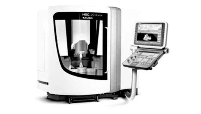
Figure 5 shows the HSC-20 Linear five-axis high-speed precision machining center produced by DMG (Germany), in which all feed axes are driven by linear motors. The rapid traverse speeds in X, Y, and Z axes reach 30 m/min, the spindle speed can reach 42,000 r/min, and it offers very high precision and reliability, capable of achieving a surface roughness of Ra < 0.2 μm.
Currently, the emergence of electric spindles and high-power torque motors has greatly simplified the structure of compound spindle heads for five-axis machining, significantly reducing manufacturing difficulty and cost, as well as narrowing the price gap of CNC systems [8].
As a result, the development of five-axis compound head type machine tools and compound machining centers (including five-face machining centers) has been accelerated.
In the field of compound machining, turning-milling technology can perform precision machining that is difficult to achieve with conventional turning for hard materials. The surface quality can rival that of grinding, and by optimizing cutting parameters, tool life can also be extended.
Today, the development of CNC machine tools has blurred the traditional distinctions between roughing and finishing processes. Machining centers now integrate turning, milling, boring, and drilling operations into a single machine.
A machining center equipped with automatic tool changers, automatic worktable changers, and automatic switching between vertical and horizontal spindle heads can not only complete boring, milling, drilling, reaming, tapping, and inspection in a single clamping, but also complete the rough and finish machining of five faces of a box-type component.
In recent years, many CNC machine tools with larger spans and more integrated functions have also emerged.
For example:
- Japan’s Ikegai Iron Works TV/4L II machining center: with a U-axis design, it can also perform turning operations.
- Toshiba’s GMC-95 vertical machining center: capable of both cutting and grinding operations on a single spindle.
- CINCINNATI MILACRON in the U.S.: developed a multifunctional manufacturing center that combines turning, milling, boring, and drilling of eccentric holes on a single machine. It can machine the outer and end surfaces of rotary parts and perform operations such as plane milling, inclined hole drilling, and curved groove cutting.
In terms of multi-axis and multi-axis control systems, Japan’s Fanuc IS system supports 2 to 15 axes, while Siemens’ 880 system can control up to 24 axes.
Major Trends in the Development of High-End CNC Systems
In the 21st century, CNC equipment will be systems with a certain degree of intelligence. The scope of this intelligence includes all aspects of CNC systems:
- For pursuing machining efficiency and quality, intelligence features include adaptive control during the machining process and automatic generation of process parameters.
- For improving drive performance and connection convenience, intelligent features include feedforward control, adaptive calculation of motor parameters, automatic load identification, automatic model selection, and self-tuning.
- For simplifying programming and operation, intelligent features include intelligent automatic programming and intelligent human-machine interfaces.
- Additionally, features such as intelligent diagnostics and intelligent monitoring have been developed to facilitate system troubleshooting and maintenance.
To address the issues of closed architecture in traditional CNC systems and the challenges in industrializing CNC application software, many countries have launched special research initiatives focused on open-architecture CNC systems, such as:
- NGC (The Next Generation Workstation/Machine Control) in the United States,
- OSACA (Open System Architecture for Control within Automation Systems) in the European Union,
- OSEC (Open System Environment for Controller) in Japan,
- ONC (Open Numerical Control System) in China.
Open-architecture CNC systems have become the future direction of CNC system development. An open-architecture CNC system refers to a CNC system that can be developed on a unified platform, targeting both machine tool manufacturers and end users. By modifying, adding, or trimming structural objects (CNC functions), series products can be created. User-specific applications and technical know-how can be easily integrated into the control system, enabling rapid development of diverse open-architecture CNC systems at various levels, resulting in distinctive and branded products.
Currently, the core areas of research for open CNC systems include architecture standards, communication protocols, configuration standards, runtime platforms, CNC function libraries, and CNC function software development tools.
Networked CNC systems primarily refer to CNC systems that are network-connected with other external control systems or host computers to enable networked control.
Typically, the networking of CNC systems begins with the local area network (LAN) of the production floor or within the enterprise, and then connects to external enterprise systems via the Internet. This is the Internet/Intranet approach.
With the maturation and advancement of networking technologies, the industry has recently proposed the concept of Digital Manufacturing. Also known as e-manufacturing, this concept is a hallmark of modernization for mechanical manufacturing enterprises and has become a standard configuration in product offerings by advanced international machine tool manufacturers.
The networking of CNC systems has further promoted the development of flexible automation manufacturing technologies. Modern flexible manufacturing systems are evolving from points (e.g., standalone CNC machines, machining centers, CNC compound machining centers) to lines (e.g., FMC, FMS, FTL, FMI), surfaces (e.g., workcell-level standalone manufacturing islands, FA), and ultimately to full systems (e.g., CIMS, distributed network-integrated manufacturing systems).
Flexible automation emphasizes easy networking and system integration, while also focusing on enhancing individual technologies. CNC machine tools and the flexible manufacturing systems they comprise can be easily connected to CAD, CAM, CAPP, and MTS systems, moving toward information integration. The development direction of network systems is toward openness, integration, and intelligence.
Figure 6 shows a new intelligent CNC system developed by the Digital Manufacturing and Measurement & Control Technology Research Institute of Tianjin University. Based on an open CNC architecture, the system achieves eight-axis, five-coordinate simultaneous machining, and also integrates on-machine quality inspection and online status monitoring.
- The on-machine quality inspection function enables real-time inspection of parts being machined, allowing for timely correction of nonconforming parts, reducing setup steps, shortening inspection time, and lowering defect rates.
- The online status monitoring function realizes intelligent monitoring and diagnosis of the entire machine tool. Combined with networking technology, it can build a remote expert system to achieve remote condition monitoring and fault diagnosis.
Figure 6: Tianjin University TDNC-H8 Open Intelligent CNC System
Siemens (Germany) has released the 840Di, an open CNC system fully integrated with a PC. Compared to its traditional 840D series CNC system, it has the following notable features:
- The CNC control functions and HMI functions run together on a PC processor, eliminating the need for a separate NC processing unit traditionally required in control systems.
- This control system includes many standardized components, such as:
- Industrial PC with interface cards,
- Windows NT operating system,
- PROFIBUS-DP communication,
- OPC interface for process control,
- NC control software.
General-Purpose CNC Systems with Bus Architecture, Full Digitalization, and Multi-Axis Multi-Channel Capabilities Have Become a Hotspot of Development
Due to the complex and variable nature of control targets and the trend toward flexible production, CNC systems need to offer flexible structural functionality with reconfigurable and customizable capabilities.
To meet this need, fieldbus technology is used to integrate function modules—each with independent control and computing capabilities—into the functional framework of the CNC system using a new optimized method and topological structure. This allows for multi-level software and hardware scalability, which has become a necessary choice for high-end CNC systems.
Full digitalization includes not only the digital connection between the CNC unit and servo interface, and internal digitization within the servo system, but also the digitization of measurement units.
Thus, fieldbus systems, digital encoder-to-servo interfaces, and digitalized triple-loop control (position loop, speed loop, current loop) inside the drive unit are important signs of full digitalization in CNC systems.
Currently, even mid- to low-end CNC systems have achieved full digital control, which has greatly improved their control precision, stability, and market competitiveness.
Figure 7 shows the GDS07 full-digital bus-based open high-end CNC system, developed by Dalian Guangyang Technology Engineering Co., Ltd. This system uses the real-time serial bus protocol GLINK and is the world’s first high-end CNC system to realize full digitalization using a single bus. The CNC system, servo units, and PLC I/O modules are interconnected via a ring topology using Category 5 twisted pair cables.
Motion data transmission between internal system components can reach up to 32 bits, supporting the needs of nano-level machining.
This system can control various machine types with two or more axes, such as:
- Turn-mill compound machining centers,
- Five-axis gantry machining centers,
- Five-axis vertical machining centers,
- Multi-axis grinding machines.
It provides system-level integrated solutions including:
- Bus-based CNC systems,
- Bus-based servo drives,
- Bus-based integrated motors,
- Bus-based PLC I/O expansion modules,
- Bus-based analog control modules.
Figure 7: GDS07 Full-Digital Bus-Based Open CNC System by Dalian Guangyang
In response to market demand in the manufacturing industry for integrated CNC machines (i.e., machines combining functions such as industrial robots, image processing systems, and precision material handling—capable of not only machining but also automatic measurement, loading/unloading, tool changing, error compensation, diagnostics, and networking), major CNC vendors have begun researching advanced functions such as:
- Multi-axis (including multi-spindle) and multi-channel control,
- Axis synchronization control,
- Axis superimposition control,
- Mixed-axis control,
- Channel collaboration.
Synchronous control ensures that motion axes across different channels act in synchronization under specific timing or conditions.
Mixed control allows hybrid commands for a single axis to be shared across channels.
Superimposition control overlays the movement command of one axis onto another axis from a different channel.
FANUC’s next-generation CNC system, the Fanuc 30i, supports:
- 10 channels,
- 8 spindles,
- Up to 32 feed axes,
- 24-axis simultaneous control,
- Concurrent execution of 10 independent CNC programs,
- Functions like axis synchronization, mixed control, and superimposed control.
Based on this system, FANUC launched an integrated processing system composed of:
- 4 handling robots,
- A gantry transportation line,
- 2 six-legged robotic machining systems.
The system operates in a coordinated, seamless, and efficient manner, representing the characteristics of a typical multi-channel CNC system.
New CNC Programming Standards Need Further Development
Traditional CNC programs mostly follow the ISO6983 (G/M-code) standard, which remains the basic programming data format used in most CNC systems.
However, ISO6983 only defines motion trajectory (G-codes) and auxiliary instructions (M-codes). It does not contain additional manufacturing information such as:
- Blank stock attributes,
- Material data,
- Tool information,
- Process data.
The lack of this information hinders data integration and automation in manufacturing processes.
To address this, the European Union launched the OPTIMAL project in 1997. This project aimed to extend STEP (Standard for the Exchange of Product Model Data, ISO10303) to the lower-level equipment in automated manufacturing by developing a STEP-NC data model as a new programming interface for milling.
This interface:
- Complies with the STEP standard,
- Has object-oriented characteristics.
STEP-NC extends STEP from product modeling into the CNC domain, redefining the interface between CAD/CAM and CNC. It enables CNC systems to directly use 3D CAD models conforming to the STEP standard, including:
- Workpiece geometry,
- Parametric configurations,
- Manufacturing features,
- Process and tooling information to generate machining programs.
Figure 8 shows the STEP-NC information model.
As an important advancement in CNC programming and data exchange, STEP-NC has become a research hotspot in the field of manufacturing automation.
Figure 8: STEP-NC Information Model
Reviewing international developments in STEP-NC technology and its applications, we find that most mainstream CNC manufacturers are participating cautiously and with a wait-and-see attitude.
It’s important to objectively evaluate the potential impact of STEP-NC on both CNC and broader manufacturing automation technologies.
However, several challenges need to be addressed before full adoption:
- Customization of process interpretation for different equipment is difficult. Most CNC equipment is customized for specific processing tasks.
- The universal modeling of CNC equipment itself remains an area requiring further research. Such models are the foundation for STEP-NC strategies and path planning.
Therefore, STEP-NC will not replace ISO6983 in the near future, but as a new international research focus in CNC, it remains worthy of continued attention.
Conclusion
From the continuous innovation in high-end CNC equipment, it is clear that fully leveraging the latest achievements in current technology fields—especially advancements in core components of machine tools and CNC systems—is the key to continually improving the manufacturing and application level of high-end CNC equipment.