


The Rise of Injection Molding in Automotive Interiors
Injection molding has become a mainstream manufacturing method for automotive interior parts due to its high efficiency, high precision, low cost and high quality.
Advanced mold design and manufacturing technology enable manufacturers to complete the process from design to production quickly to meet the needs of car companies.
This manufacturing method can also ensure that the product appearance, compact structure.
Product Profile: CD Player Inner Shell
The car laser record (Compact Disc, CD) machine is a car interior part.
Although, it rarely used nowday, obsolete products, still as a good example for beginner.
It needs to ensure basic functionality, have good surface quality, and maintain low cost.
Therefore, the injection molding process is suitable for its manufacturing.
Although this product is now obsolete, its mold design remains valuable for teaching and training. Beginners can carry out the design to learn the process.
Plastic parts structure analysis
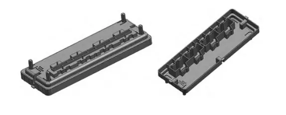
Plastic parts for the CD machine shell, the structure of the shape shown in Figure 1.
The size of the product is 180 mm×63 mm×20 mm, the maximum wall thickness is 2.19 mm, the minimum is 1.1 mm, and the average wall thickness is 1.5 mm.
The product has uneven wall thickness and a complex shape.
It requires high surface quality and dimensional accuracy.
It also includes many detailed features, such as jacks, slots, reinforcement bars, and various other small structures.
Considering cost, manufacturers use Acrylonitrile Butadiene Styrene (ABS) plastic for the product.
This material has a shrinkage rate of 0.5%, a melting temperature of 181–229 °C, a molding temperature of 82–134 °C, a molding pressure of 101–131 MPa, and requires a medium injection speed.
Mold Design
Design of parting surface
The design of the parting surface largely determines the quality of the mold.
A good parting surface can ensure the product’s good performance and appearance.
It facilitates the processing of the parts, makes mold release easier during ejection, allows smoother exhaust, and helps lower manufacturing costs.
The part requires high surface quality, the appearance should minimize the parting line.
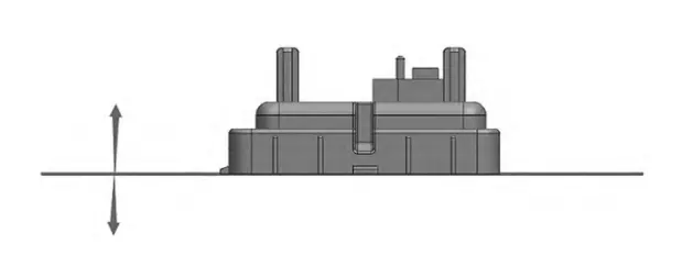
The height of the part is 29.18 mm, and all four faces are simple and regular, but there are holes in the faces.
The slider needs to extract these holes to release the mold properly.
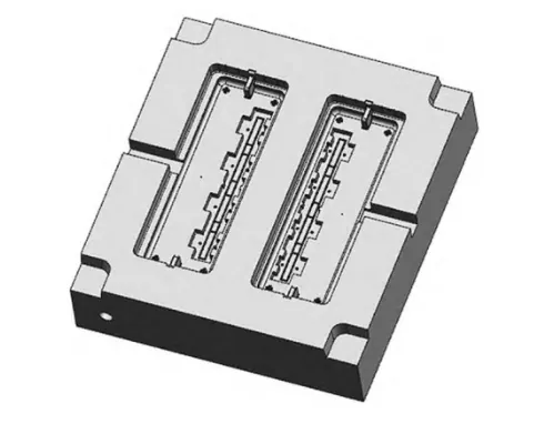
Figure 2 shows the parting plan of the mold, with the designer placing the parting surface on the upper surface of the product cavity.
After parting, the mold shapes the outer surface of the product through the cavity and forms the inner surface through the core.
Pouring System Design
Main runner design
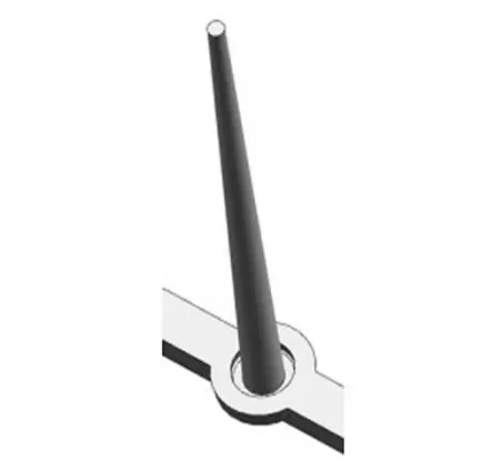
The shape of the main runner is a round table, as shown in Fig. 3.
The diameter of the small end of the main runner is generally 0.5 to 1.0 mm larger than the nozzle diameter of the injection molding machine.
In this case, the nozzle diameter is set at 1.0 mm.
Known as the injection molding machine nozzle diameter of 2.5 mm, the diameter of the small end of the main flow channel is 3.5 mm.
The design of the main runner needs to consider the ease of demolding, general demolding slope α, take 1 ° ~ 2 °.
The designer sets the height of the main runner to 95 mm and the diameter of the big end to 8.5 mm.
Diverter design
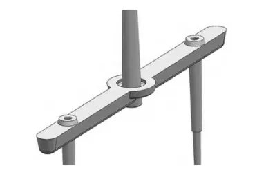
The shape of the manifold is trapezoidal, as shown in Fig. 4.
The diameter D of the cross-section tangent circle of the manifold can be calculated by the empirical formula.
The empirical formula is

Where : m is the mass of the molded part, the mold structure is a two-cavity mold, the mass of a single part is 28.78 g, and the total mass of the molded part is 57.56 g; L is the length of the manifold.
L is the length of the manifold, 75 mm, and D is about 5.9 mm by substituting the relevant data.
Therefore, the top width of the manifold is 9.5 mm, the bottom width is 6.7 mm, and the height is 8.0 mm.
Gate Design
The most important aspect of the gate design is to ensure the filling of the plastic melt.
For medium-sized parts, the gate should be wider and slightly higher.
Designers should locate the gate in the center of the part.
Based on the above analysis, designers should design the gate of the mold as a point gate.
They should determine its size according to the volume of the part and the size of the manifold.
Ask ChatGPT
The width of the gate should be smaller than the diameter of the manifold, which is 1.2 mm, and the height is 0.8 mm.
Design of molded parts
Cavity design
Designers place cavities on one side of the mold plate and mainly divide them into two types: integral type and inlay type.
Integral cavity refers to the cavity directly machined on the template, the cavity strength is good, easy to process, but not easy to replace and repair, suitable for the surface quality requirements of the molded part is not high; and inlaid cavity refers to the cavity directly machined on the template.
The inlaid cavity refers to the combination of multiple parts into the cavity, easy to process, repair and replacement.
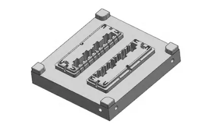
Therefore, the mold adopts inlaid cavity, the specific structure shown in Figure 5.
Cavity radial size LM calculation using the average size method, the formula is
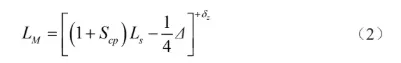
Where:
Scp for the average shrinkage of the molded part, 0.005; .
Ls is the nominal radial dimension of the part, mm.
Δ is the tolerance value of the part, mm.
δz is the manufacturing tolerance, mm.
It is known that the nominal size of the length of the product is 173 mm, and according to the literature, the tolerance Δ is 0.36 mm, then the manufacturing tolerance δz of the cavity is 0.12 mm, which can be calculated by substituting into the formula (2) to obtain the radial dimension of the cavity LM is 173.78+0.12 mm.
Cavity depth HM is calculated using the average size method, the formula is
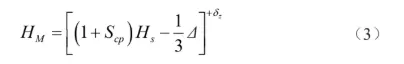
Where: Hs is the nominal size of the height of the molded part.
Hs is the nominal size of the height of the molded part, mm.
The nominal size of the height of the product is 28 mm, and the tolerance Δ is 0.15 mm according to the literature, then the manufacturing tolerance δz of the cavity is 0.05 mm, which can be calculated by substituting into the formula (3) to get the depth of the cavity HM is 28.09+0.05 mm.
Core Structure Design
The core is fixed on the moving template. The mold adopts inlaid core structure, as shown in Fig. 6.
The radial dimension 𝑙M of the core is calculated by the average size method, the formula is
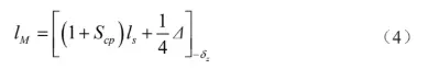
where : 𝑙s is the nominal dimension of internal cavity length, which is 167 mm.
According to the literature, the tolerance Δ is 0.36 mm, then the radial manufacturing tolerance δz of the cavity is 0.12 mm, which can be calculated by substituting into Eq. (4) to obtain the radial size of the core 𝑙M is 167.93-0.12 mm.
The core depth hM is calculated by the average size method, and the formula is as follows
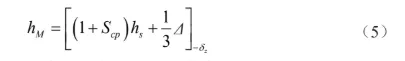
where :hs is the nominal dimension of the internal cavity height, which is 30 mm.
According to the literature, the tolerance Δ is 0.15 mm, and the manufacturing tolerance δz of the cavity is 0.05 mm. Substituting into Eq. (5), the core length hM is 30.20-0.05 mm.
Calculation of molded part thickness
Engineers calculate the stiffness of the side wall of the mold core as follows.
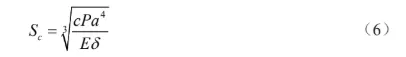
Where: Sc is the thickness of the side wall of the mold core.
Sc is the thickness of the side wall of the mold core
c is the safety coefficient, take 1.5; P is the average cavity molding pressure, take 1.5 after checking the table.
P is the average cavity molding pressure, take 30 MPa after checking the table.
a is the height of the part subjected to melt pressure, 16 mm.
E is the modulus of elasticity of steel, 2.1×10⁵MPa.
δ is the permissible deformation of the material, take 0.005.
The thickness Sc of the side wall of the mold core is about 14.11 mm.
Considering the interference of other factors, the value of the thickness of the side wall of the mold needs to be larger.
Cooling system design
The cooling system can make the molded part cool down quickly and improve the strength and stiffness of the molded part.
Designers generally design the system as a wrap-around type because it is easy to process and achieves a good cooling effect.
Cooling system needs cooling water flow calculated as follows
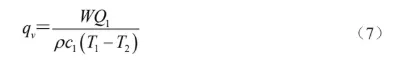
In: qv is the volume flow rate of cooling water.
qv for the volume flow rate of cooling water, m3 ∙ min-1;.
W is the unit time injected into the mold plastic mass, kg ∙ min-1;
Q1 is the heat released per unit mass of plastic product during solidification, kJ ∙ kg-1 .
ρ is the density of cooling water, 1 × 10³ kg∙m-3.
c1 is the specific heat capacity of the cooling water, 4.2 kJ∙ kg-1 ∙ °C-1 .
c1 is the specific heat capacity of cooling water, 4.2 kJ∙ kg-1∙ °C-1 ; T1 is the outlet temperature of cooling water, °C; T2 is the inlet temperature of cooling water, °C.
The injection time is 2 s, the cooling time is 20 s, the holding time is 15 s, and the mold opening time is 3 s. The cycle time of injection molding is 40 s.
If the injection time is 2 s, the cooling time is 20 s, the holding time is 15 s, and the mold opening time is 3 s, then the cycle time of injection molding is 40 s.
Let 20 ° C water as the cooling medium, its outlet temperature is 28 ° C, the water is turbulent, the number of times per hour molding is 90 times, an average of 1.5 times per minute.
Known as W is 0.091 kg ∙ min-1, check the injection mold design guidebook can be obtained, the unit mass of ABS plastic solidification heat released for 310 ~ 410 kJ ∙ kg-1, the calculation of the average value of 360 kJ∙ kg-1.
Substituting the relevant data into equation (7), qv is about 0.001 m3 ∙ min-1.
According to the calculated cooling water flow rate, the diameter of the cooling water channel should be 8 mm by consulting the injection mold design guidebook.
Design of Ejector and Reset Mechanisms
Ejector design
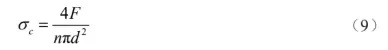
The ejector mechanism consists of spring, pusher, face plate and bottom plate, as shown in Fig. 7.
When designing the ejector pin and tilt top, attention should be paid to the appearance quality of the product, and whether it is easy to be processed should also be considered.
The formula for the mold release force of the plastic part is

In the formula, F is the mold release force, N;.
F is the mold release force, N; for the molded part including the side area of the core, take 583 mm2; p is the molded part to the core unit area, take 583 mm2.
p for the molded part of the core unit area of the clamping force, generally 8 ~ 12 MPa, calculated to take 10 MPa; μ for the plastic on the steel of the core of the package force, the calculation is 10 MPa; μ for the plastic on the steel, the calculation is 10 MPa.
μ is the coefficient of friction of plastic on steel, generally 0.1 ~ 0.3, calculated as 0.2; α is the coefficient of friction of plastic on steel, generally 0.1 ~ 0.3, calculated as 0.2.
α is the multi-mold slope of the plastic part, take 1°.
Substituting into the relevant numerical calculations can be obtained demolding force F is 874 N.
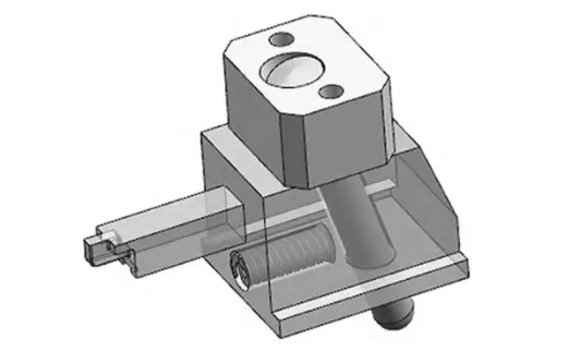
The strength of the push rod is calculated as follows
The formula of push rod strength is
The formula: σc is the strength of the push rod.
σc is the stress on the pusher; n is the number of pusher, take 1°.
n is the number of pushrods, take 48 pcs; d is the diameter of pushrods, take 48 pcs.
d is the diameter of push rod, take 1.5 mm.
Substituting into the relevant numerical calculation, we can get σc is 45.87 MPa.
It is known that the permissible stress [σ] of the actuator material is 120 MPa, σc < [σ], which means that the strength requirement of the actuator is satisfied.
Design of the reset mechanism
The reset mechanism consists of two parts: the reset lever and the spring.
Manufacturers generally use SKD61 for the reset lever and can use standard parts.
Designers arrange the springs at the corners of the reset mechanism.
They determine the spring length based on the distance from the end face of the face plate to the bottom face of the moving template—generally 30 to 50 mm, and 30 mm for small and medium-sized molds.
Design of side core pulling mechanism
As there are side holes on the side wall of the product, it is necessary to use the side core pulling mechanism to complete.
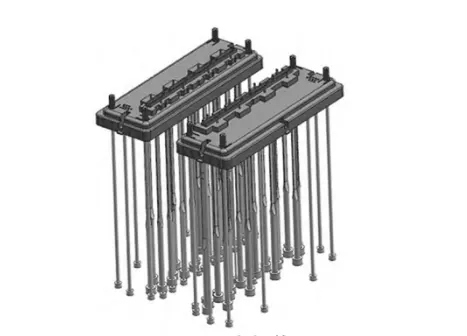
The mold adopts the slanting guide pillar / side slider core pulling mechanism, as shown in Fig. 8.
When the mold opens, the slide moves along the inclined guide column.
The slide’s movement decomposes into vertical and horizontal components.
The horizontal movement enables the lateral core extraction.
The core pulling distance is 3~5 mm longer than the buckling distance of the molded part, this design takes the middle value and designs the core pulling distance as 16 mm.
The calculation formula of the core pulling force Fc is as follows

A1 is the wrapping area of the molded part on the slide, 135×10-3mm2; p1 is the area of the molded part on the side of the molded part, 135×10-3mm2.
p1 is the wrapping force per unit area of the core on the opposite side of the part, generally taken as 1×10³ Pa; μ is the wrapping force of the part in hot assembly.
μ for the molded part in the hot load on the steel friction coefficient, take 0.2; 𝒂 for the slider core on the friction coefficient, take 0.2.
𝒂 for the slider core demolding slope, generally take 20 °.
Substituting into the relevant numerical calculations can be obtained Fc is 120 N.
The formula for the diagonal guide pillar diameter d is
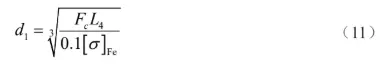
Where : L4 for the effective length of the oblique guide column, take 25 mm; [σ] Fe for the permissible bending stress of carbon steel, take 137.2 MPa.
Substituting into the relevant numerical calculations can be obtained oblique guide pillar diameter d1 is 11.52 mm.
Selection of standard mold frame
Because the molded part has a simple structure, designers use a standard mold for the mold frame.
The selected mold type is three-plate mold FCI. The size of molding cavity is 220 mm×240 mm×60 mm, the size of molding core is 220 mm×240 mm×51 mm, the size of fixed template of the mold frame is 450 mm×450 mm×100 mm, the size of moving template of the mold frame is 450 mm×450 mm×80 mm, and the height of the cushion is 120 mm.
Based on the casting system structure and ejector release requirements, designers select the national standard mold frame.
Designers adopt the simplified fine spout mold frame system and select the specific mold frame model FCI-4545-A100-B80-C120-L340.
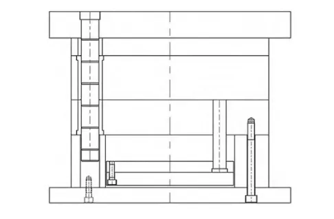
Figure 9 shows the completed mold structure.
Conclusion
Based on the use environment, technical requirements of the CD player’s inner shell, and analysis of the product’s material and structure, designers determine the mold design scheme.
The mold design is both economical and practical, which provides a strong guarantee for the production of high quality and low cost of the inner shell of automobile CD player.